 .....
.....
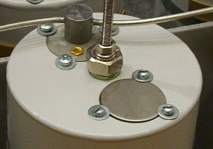
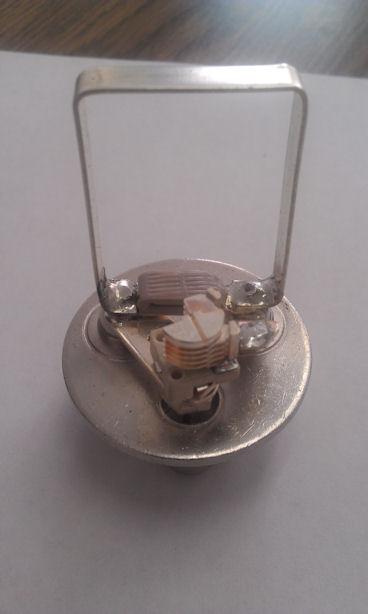
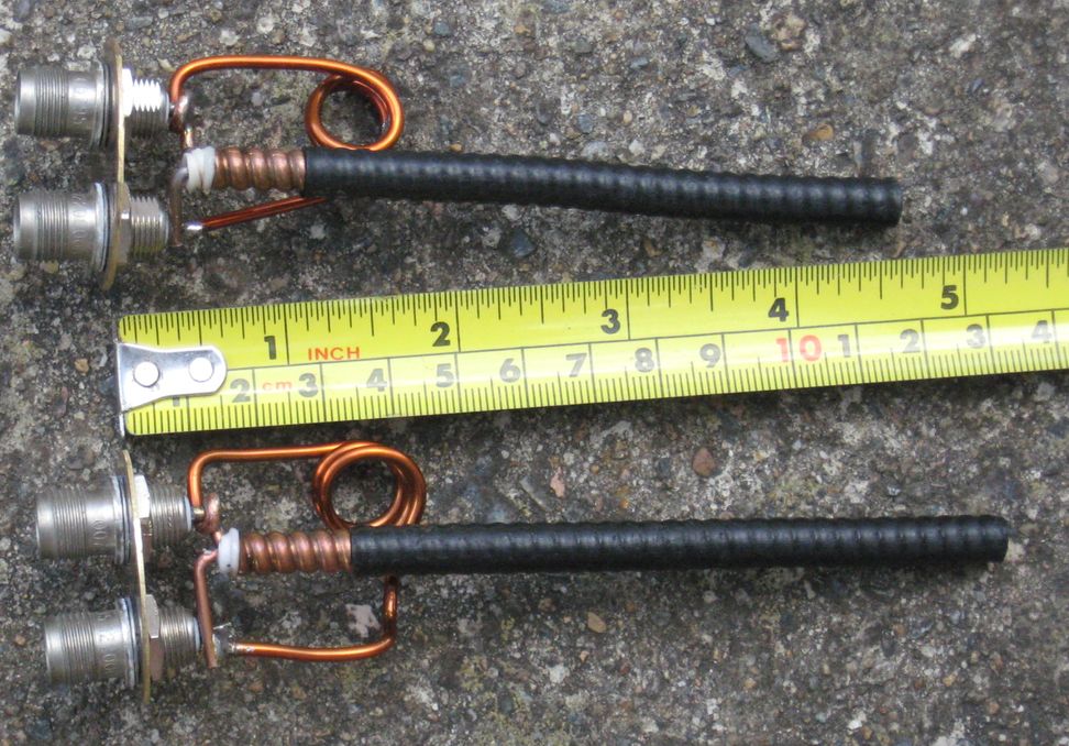
Note: No connectors, hardwired and Gold trimmer.
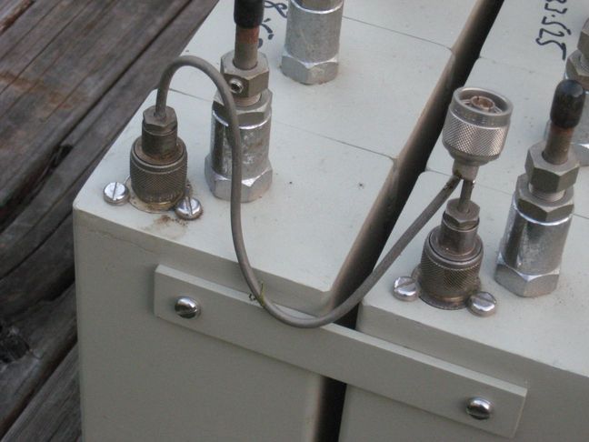
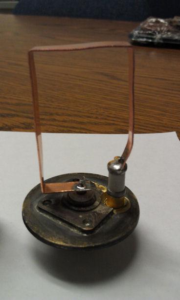
1) The single connector series loop and trimmer to GND type.
2) The two connector, couple a bit of energy between the coupling loops
with either L or C.
3) The two connector, couple some energy magnetically between loops.
4) The two connector, parallel resonant circuit between connectors.
5) The single connector capacitor divider, with either L or C in the GND side.
As in the 2" heliax duplexer for 6m.
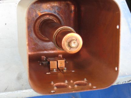
AND, the aperture coupled Band Pass UHF cavities behind the image
Ant_Tee_IMG_3734b.jpg.
.....
Note: No connectors, hardwired and Gold trimmer.
 Note phase swap of LHS loop, makes for larger L.
 Magnetic coupling.
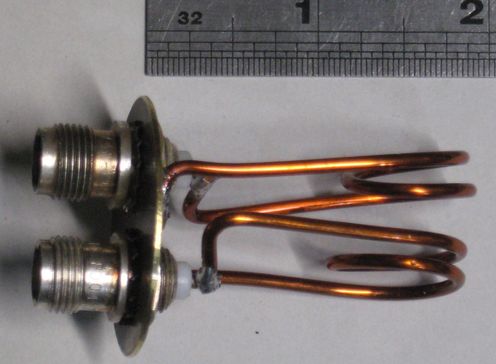 Pass then Notch, 2x 195mm
 Notch then Pass, 2 wires 2mm x 205mm Coil ID 14mm.
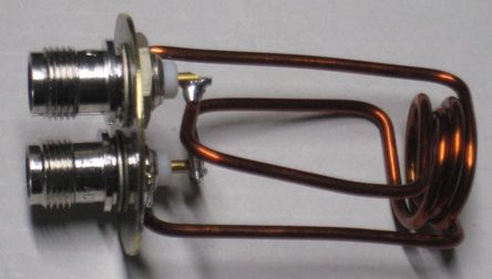
 Two connectors parallel resonant circuit between.
Three adjustments, cavity plunger, rotate probe assy., adjust cap.
 Note the caps between the connectors.
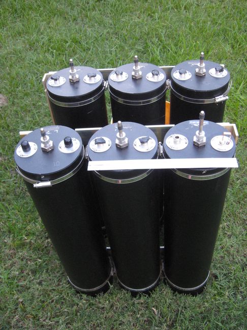
4x 5" cans in the 19" rack nice, I question if it is good enough for our 600KHz spacing?
Can't be Wacom WP639 or WP641, no down the side coaxial stub
Tx noise supp. at Rx freq. 80 dB at 0.6 MHz, 90 dB at 2 MHz
Rx isolation at Tx freq. 80 dB at 0.6 MHz, 90 dB at 2 MHz
See A 1972 article on 2" heliax as resonators for 6m also on UHF the Motorola T1500
At the notch frequency, types 1 and 5 (above) present a Very Low impedance thus back at the antenna "T" where we need a High impedance as the energy at this frequency is to go straight past, we can use a quarter wavelength line to achieve this.
Type 4 presents a High impedance at the notch frequency so half wave lines are
used to the Antenna "T". Between cavity lines, see Ref (h).
Types 2 and 3 and the Band Pass cavities present a High VSWR but neither High or
Low impedance exactly, this is where it gets hard. A Vector Network Analyser is a great tool here but I doubt they had one back in the 1960s. Instead, General Radio Inc. made a constant impedance adjustable line. Adjusts 20cm and they would
have used other known lengths of coax to calibrate it.
The LHS of my picture Ant_T_IMG_3734b.jpg has an extra half wave of hard-line to
get the lengths right (as best I could).
Between cavity lines
Type 1 (Series to GND) are easy, 1/4 wave. Others can cause interaction between the cavities such
as Type 4.
A Vector Network Analyser should be used at this point. But, can we get away without one with
our choice of cavity type. The BIG question.
So, now you know why some of the coax lengths are not quite quarter wave or half
wave. Particularly where the Rx and Tx chains join, the Antenna T.
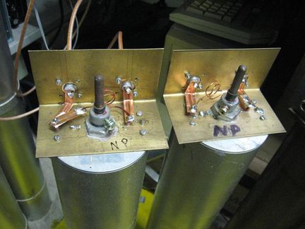
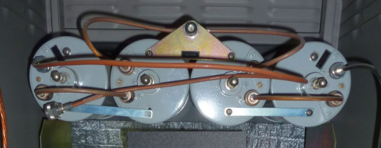
Some examples of home-made (type 4) coupling loops for 6" RFS or AEA cavities.
 IMG_3733b.jpg TNC connectors
The cavity set pictured below.
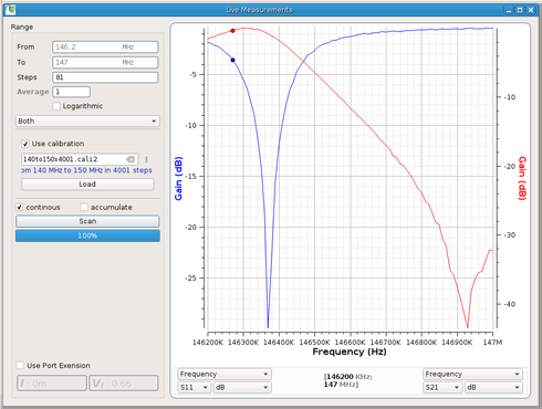
I've made up the loops, set them up for 146.9MHz pass and 146.3 notch, make up all
the 1/4 and 1/2 wave patch leads, connect it all up, this chain works, a treat. But, the other set,
individually look good but together, the pass is a double hump and 6db down. What do I do?? I tried putting a bandpass cavity between the two BP-BR cavitiies, no effect. I tried a 5db pad from the VNA, no effect.
OK then, how do we fix it? 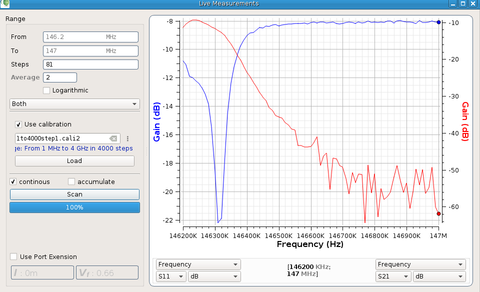
 Magnetic coupling, Type 3, RHS picture above.
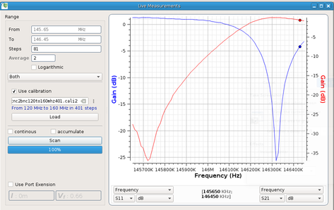 Magnetic coupling, Type 3, Lower picture above.
Both can be done, pass then notch, notch then pass.
 Magnetic coupling, Type 3, Lower picture above.
This is with about 4" of connectors added inline from the calibration point.
a) A 1972 article on 2" heliax as resonators for 6m
b) A 1965 IEEE article by Phelps Dodge
c) A general article by EMR Corp
d) A 2010 article by Sinclair
e) Where the loop cannot be rotated...VE2AZX
f) Motorola T1500 UHF series, with internal pictures.
g) TX-RX Coupling Loop Project on the Repeater Builder website but no followup on a full duplexer build.
h) TX-RX-instruction-manual-vari-notch-duplexers-with-6-inch-cavities.pdf 1/4 wave inter-connect cables, not quite correct.
i)
andrew-about-rf-communications.pdf Section 4, a general article.
j) Hybrid rings from 1966
k) Vari-Notch patent
l) Chapter on the Hybrid Ring by W2EUP
m) Duplexers, Theory, and More by I1WQR
n) My page on the Hybrid Ring
o) GE M2 comparison Tx PLL to Tx multiplier systems (VHF)
Alan VK2ZIW