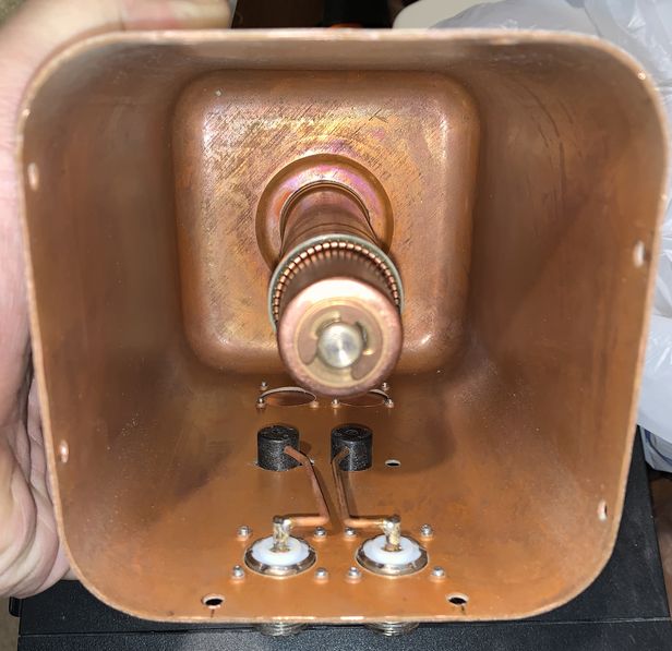
Note, the above picture does not have the UHF barrel joiner.
Snippets from http://www.repeater-builder.com/motorola/t1500/t1500.html
Note, the above picture does not have the UHF barrel joiner.
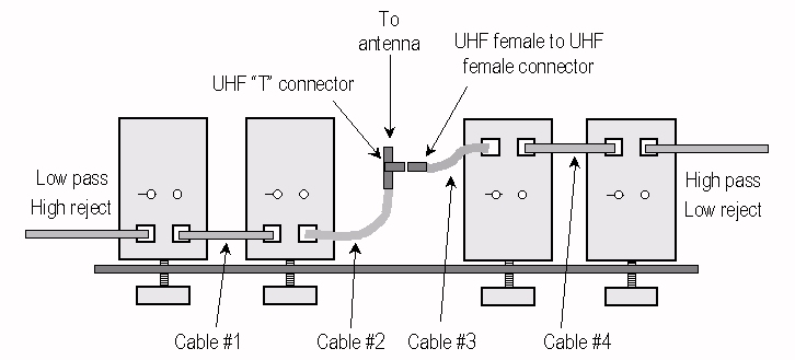
| Cable lengths in inches, from tip of PL259 to tip of PL259 Teflon coax as pictured. Note the UHF barrel used #3 | ||||
|---|---|---|---|---|
| Table from RB website | Cable #1 | Cable #2 | Cable #3 | Cable #4 |
| 406-430 MHz | 9-3/8 | 9-3/4 | 6-3/4 | 10-1/2 |
| 430-470 MHz | 8-1/2 | 8-3/4 | 5-3/4 | 9-3/4 |
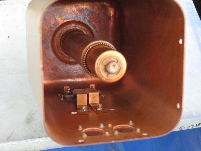
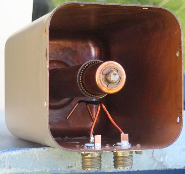
In this document from RepeaterBuilder, the pictures are not that clear.
T1500 manual version "G" dated 01/25/1983 1.3
MB PDF file
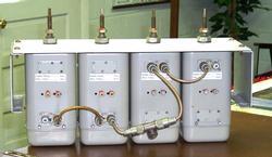
From the RB email group: Scale, pictures taken on the outside of a T1500 cavity.
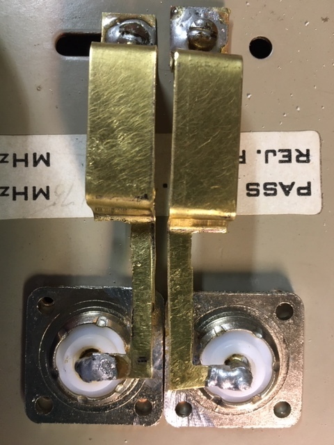
Capacitive Coupling below
Magnetic Coupling below
Below from Jim K9AGR
This below did not work, I was following a very very poor picture
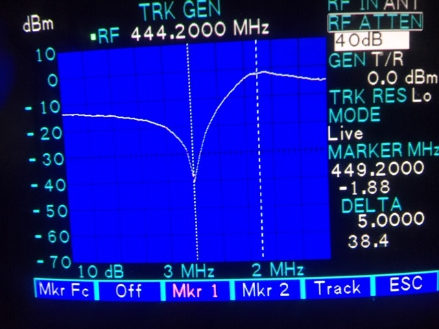
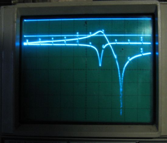
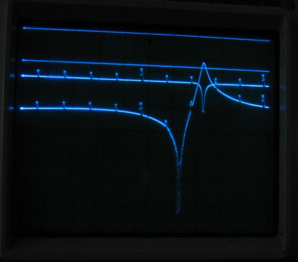
Below some scans of "cap" and "mag", T1500 cavities, 5 MHz blips, 10db / cm.
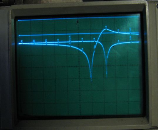
Above Capacitive coupling at the hot end, below Magnetic Coupling.
Insertion loss, < 1db.
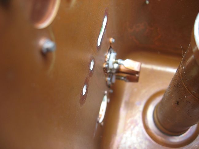
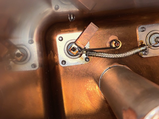
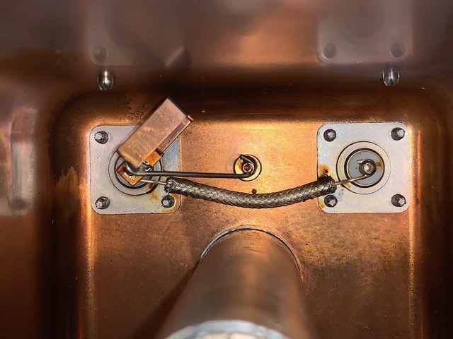
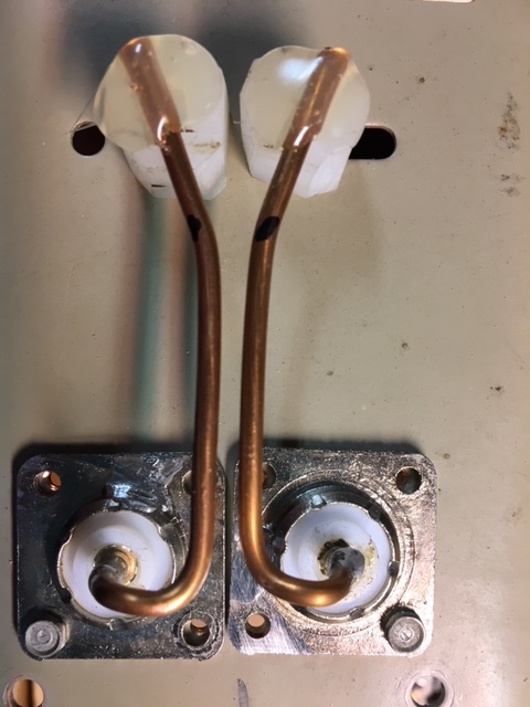
Note the piston trimmer and the coax between connectors.
"T" pieces are problematic, this is a way to avoid them.
Note the coax outer soldered to the connector grounds.
The series resonant loop to GND with coupling to some of the coil.