Notes on 70cm Duplexer Cavities for HAM bands
70cm 1-2% freq spacing, 6m 1MHz 2% spacing, 2m 600KHz or 0.4% spacing, 10m 100KHz 0.34% !
Note, none of the commercial units I've seen use the
couple a bit of energy from one connector to the other
approach.
 IMG_3709can.JPG
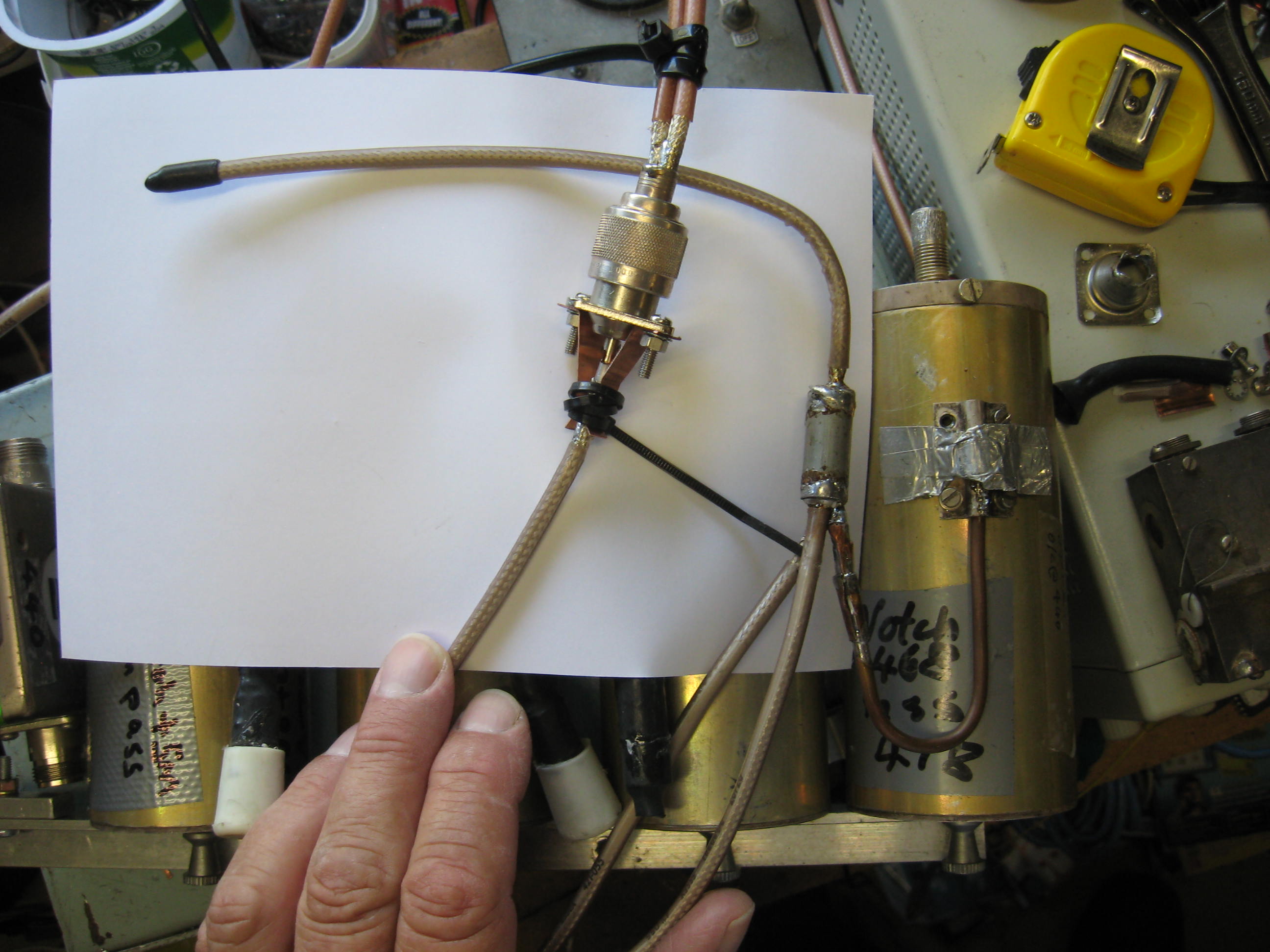
1/4 wave lines can be used to swap the pass and notch frequencies,
also to have a high impedance at the near end, at the antenna "T".
Note the "U" of hard-line, this is the 1/4 wave notch/pass swapper.
Note also the 1/2 wave piece heading left. And, the 3/4 wave to the antenna "T"
(cable ties). Here I test it with my "pass by" cable. (2 coaxes into an "N" plug)
The coax under my hand, 3/4 wave, is about the right length.
At 70cm (440MHz), 10mm of coax or a connector makes quite a difference.
 IMG_3711plot.JPG
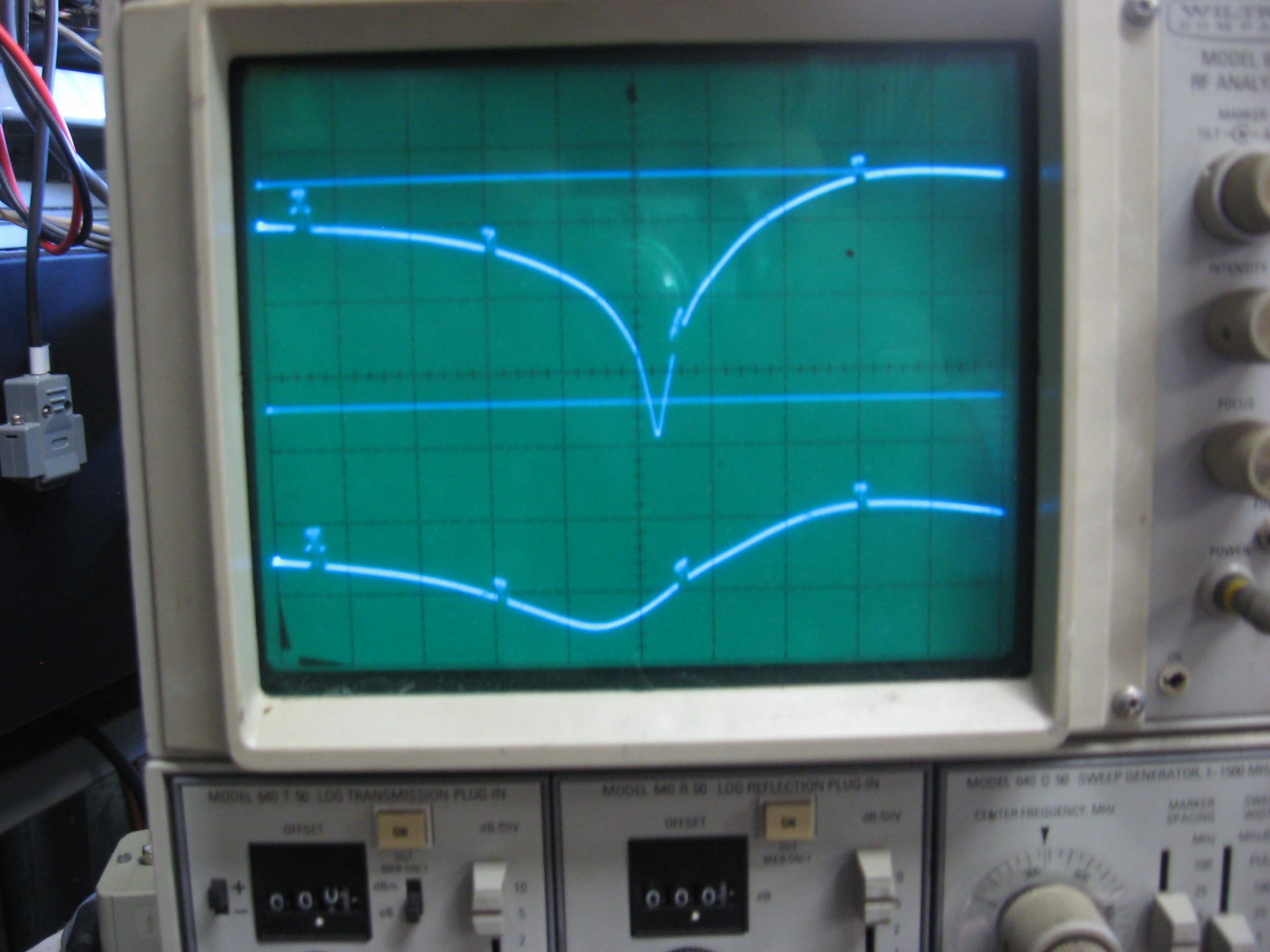
Top trace the notch, markers at 5MHz. Bottom trace is "pass by" Return loss.
Note above, the notch frequency is below the pass ~8MHz.
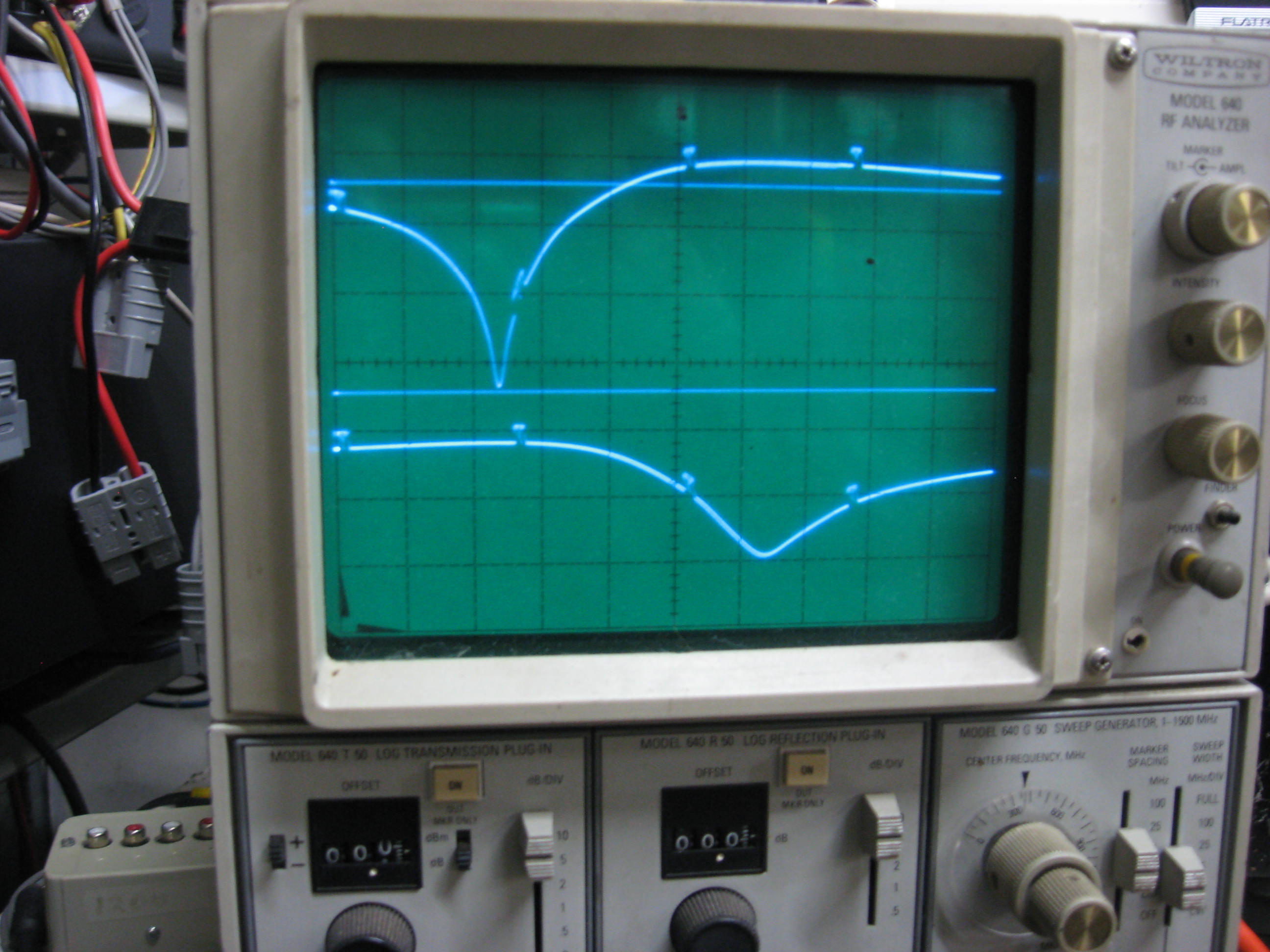
Next below is the plain notch and pass plot, return-loss lower trace
Clearly the notch is about 8MHz below the pass.
 IMG_3712plot.JPG
=========== Notch to Pass spacing =============
At this point, I'm not sure about the coax length to the cavity coupling loop.
That 1/2 wave stub resonates at 440MHz which is about 20MHz lower than the original notch frequency. Perhaps it's purpose is to improve the SWR at the "pass by" frequency.
Let's look at the other three cavities: