|
|
|
|
FT-897 mods
View
PDF mods file
1 Remove the 8 screws affixing the top panel of the transceiver
and gently
lift it off.
2 Carefully remove the small 2-pin speaker plug from the left rear
corner
of the transceiver interior, then remove the heavier 6-pin plug from
the
connector inside the right side of the transceiver.
This can be removed by pushing on the tab to release the connector.
3 Locate the nine jumpers. These are located about 2" from the
front edge
of the main unit and about 3/4" from the left edge. You now have a
choice of 2 different mods:
For 144/430MHZ TX expansion only, remove the jumper at JP1002, leaving
the other jumpers alone. For the complete expansion per the above
listing, place jumpers at JP1007/1008/1009, and remove the jumpers at
JP1001/1002/1003/1004/1005(leave the jumper at JP1006 in place). Note
the unusual sequence for the numbering. With the front of the rig
facing
forward, from the front of the rig to the back, the numbers of
the jumpers are as follows: 1003,1002,1001,1006,1005,1004,1009,1008,
1007.
Result of radio should look like below after FULL mod was done:
----BACK OF RADIO------
1007 - Jumper
1008 - Jumper
1009 - Jumper
1004 - Blank
1005 - Blank
1006 - Jumper
1001 - Blank
1002 - Blank
1003 - Blank
----FRONT OF RADIO-----
4 Replace the top panel
5 With the transceiver off, press and hold the [F] and [V/M] keys;
while
holding them in, turn the radio on. Modification is now complete.
6 The radio is now complely reset to all the original factory
settings
except that it now is able to transmit 1.8-56 MHz, 137-164
MHz, and 420-470 MHz. You will need to reprogram all the menu
operations
and memory channels
| YAESU
FT-897 / FC-30 Fan modification |
I use the FT-897 with the
optional Antenna-Tuner FC-30.
It always makes me nervous if a
fan is running, but in modern
rigs it seems to be a normal
(annoying) thing. Nevertheless
this waste valuable energie when
you use the FT-897 as a portable
with its internal NiMh-Accus.
If the FC-30 is connected its
fan runs all the time - thats
needlessly ! So I decided to
integrate a temperature-switch
...
I found a small circuit at
www.conrad.de with the order no.
114421, sized like a stamp. You
only have to cut the fan wireing
and integrate this circuit -
very easy.
Adjust the circuit that it
switched off the fan at a normal
(room-)temperature. A LED is on
the module ... its very helpful
and there is no need to connect
the fan for adjustment.
Then place the
temperature-sensor near the coil
in the FC-30; - I fixed the
circuit with double-side tape.
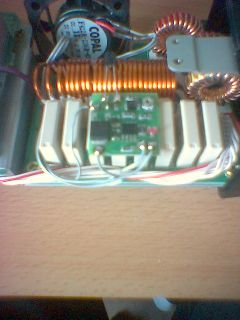
Thats all ! |
|
|
|
|
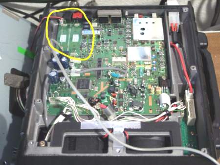
| Mars/Cap mod
for Yaesu FT-897 |
-
1- Remove top cover of radio
being careful to remove
speaker and battery switch
connectors.
-
2- Locate Q1049 number on
chip is HD64F2134FA20..
There are 9 solder pads
connected to this chip
through D1044, D1047, and
D1048. On my radio pads 6,
7, and 8 are populated.
Number 1 pad would be closer
to the rear of the radio.
-
3- Populate pads 1, 2, and 3
with a piece of fine wire or
just bridge the gap with
solder.
-
4- Reset the radio by
pressing and holding "V/M"
and "F" buttons while
turning on the radio. You
will hear a series of beeps.
After mod radio will transceive
1.8-56 MHz, 137 |
|
|
|
|
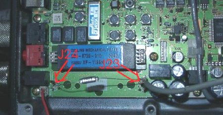
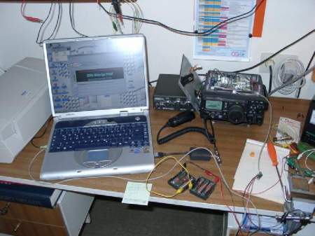
| DRM
modification for Yaesu FT-897 |
| FFor
recieving DRM we had the
following equipment:
Remove the upper cover from the
transceiver.
Look for the slots for optional
CW or SSB filter (backside,
left)
It’s labelled: J24 and J23
Bridge the left two pins of J24
– so the software will use this
slot as if the SSB filter is
installed.
Put a 120 pF capacitor between
the right pin of J24 and the
right pin of J23. The third pin
of J23 is connected to ground.
Connect the DRM mixer module to
the two right pins of J23
(ground and 455 kHz IF in) – see
page 3 (1) and
(2).
You can get the voltage for the
mixer from the right backside of
the transceiver (only + needed).
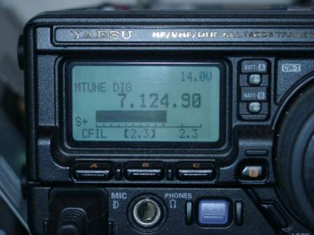
For using the DRM receiver you
have to use the 2.3 kHz optional
Filter setting in Menue N
(that’s the reason for the J24
jumper).
Opened transceiver:
Filter slots:
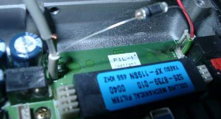
FIL-1 schematic:
 |
|
|
|
|
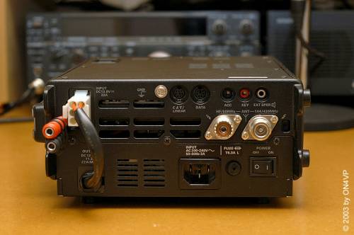
| FT-897 mod
for SGC-230 DC power |
the FT-897 a lot with the
SGC-230 smartuner, a fine
combination. Because I installed
the optional power supply and
also when operationg on a DC
battery, I wanted a easy
solution to power my SGC-230.
-
Remove bottom cover or
optional power supply FP-30
-
Locate the red and black
wire for main power supply
to board
-
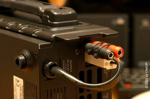
Insert two short wires
through the smal hole next
to the power socket
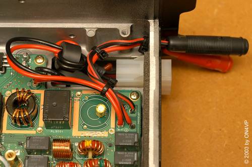
-
Solder those two wires (red
& black) onto the board,
there are two free
solderpoints below the power
cords
-
Secure the soldered wires
against pulling with small
straps (also just behind the
chassis)
-
Replace the bottom cover or
power supply.
-
You can additionally use
smal straps to align the two
female DC connectors.
I used 0.75mm² wire so I have
more than enough current without
risk. You could insert an extra
fuse for further protection.
The SGC-230 takes up 0.9 Amps
while operation. Other models
even use less current.
The mods is very easy to carry
out and doesn't require high
skills, but I recommend using a
decent soldering iron.
This mod is great, now I can
hook up my SGC-230 (or even
another low current device) in a
very compact and decent way.
The mod can be easely reversed
if needed.
|
|
|
|
|
|
FT897/857/817 Jumpers by Software |
|
The small program is to update
the Jumper settings for the
Yaesu FT897, FT817 and FT857 via
the CAT interface.
It is
available in the FT897 group on
yahoo:
http://groups.yahoo.com/group/FT897/files/softjump.zip
This program allows you to
perform the jumper modification
without modifying the hardware
on your radio. |
|
|
|
|
| Installing
The FT-897 Options |
| FT-897
Second Menu (Adjustmenu) fuctions |
|
Their is a second set of menu
functions F01 to F74.
WARNING: changing these
will reset all the memories.
I want to warn you do not change
these values unless you are sure
of what you are doing. To get
them turn transceiver off. Press
and hold the A,B,C keys; while
holding them in, press and hold
in the [PWR] switch for 1/2
second to turn the tranceiver
On. Now let go of all keys. Then
press and hold func key for 1/2
second to get to the menu and
then rotate the select knob to
get to a second menu (F01 to
F74). When you turn the rig off
and back on it returns to normal
menu. Here is a list of the 74
second menu functions.
Function Setting in my radio
=============================================================
Adjust-No      Function            Setting  Mode    Frequency
=============================================================
NO-001         HF1-RXG             118        CW     1.800.00
NO-002         HF2-RXG              91         CW     7.068.19
NO-003         HF3-RXG             133        CW    21.225.13
NO-004         50M-RXG             106        CW    50.000.00
NO-005         VHF-RXG             77         CW   145.437.50
NO-006         UHF-RXG            103        CW   438.900.00
NO-007         SSB-S9                  61         CW    21.225.13
NO-008         SSB-FS                  54         CW    21.225.13
NO-009         FM-S1                   68         FM   145.437.50
NO-010         FM-FS                   99         FM   145.437.50
NO-011         DISC-L                  50         FM   145.437.50
NO-012         DISC-H                 79         FM   145.437.50
NO-013         FM-TH1              100        FM   145.437.50
NO-014         FM-TH2              100        FM   145.437.50
NO-015         FM-TI1                 10         FM   145.437.50
NO-016         FM-TI2                 10         FM   145.437.50
NO-017         VCC                     138        FM   145.437.50
NO-018         HF1-IC                 83         CW     1.800.00
NO-019         HF2-IC                 80         CW     7.068.19
NO-020         HF3-IC                  87         CW    21.225.13
NO-021         50M-IC                 84         CW    50.000.00
NO-022         VHF-IC                 72         CW   145.437.50
NO-023         UHF-IC                74         CW   438.900.00
NO-024         HF1-PO-MAX          165        CW     1.800.00
NO-025         HF1-PO-MID2         105        CW     1.800.00
NO-026         HF1-PO-MID1         31         CW     1.800.00
NO-027         HF1-PO-MIN          13         CW     1.800.00
NO-028         HF2-PO-MAX          159        CW     7.068.19
NO-029         HF2-PO-MID2         102        CW     7.068.19
NO-030         HF2-PO-MID1         29         CW     7.068.19
NO-031         HF2-PO-MIN          11         CW     7.068.19
NO-032         HF3-PO-MAX          158        CW    21.225.13
NO-033         HF3-PO-MID2         101        CW    21.225.13
NO-034         HF3-PO-MID1         29         CW    21.225.13
NO-035         HF3-PO-MIN          11         CW    21.225.13
NO-036         50M-PO-MAX          145        CW    50.000.00
NO-037         50M-PO-MID2         92         CW    50.000.00
NO-038         50M-PO-MID1         47         CW    50.000.00
NO-039         50M-PO-MIN          8          CW    50.000.00
NO-040         VHF-PO-MAX          87         CW   145.437.50
NO-041         VHF-PO-MID          43         CW   145.437.50
NO-042         VHF-PO-MIN          7          CW   145.437.50
NO-043         UHF-PO-MAX          112        CW   438.900.00
NO-044         UHF-PO-MIN          16         CW   438.900.00
NO-045         HF1-TXG             48         USB    1.800.00
NO-046         HF2-TXG             38         USB    7.068.19
NO-047         HF3-TXG             43         USB   21.225.13
NO-048         50M-TXG             40         USB   50.000.00
NO-049         VHF-TXG             47         USB  145.437.50
NO-050         UHF-TXG             49         USB  438.900.00
NO-051         ALC1-M              203        USB   21.225.13
NO-052         ALC-M               85         USB   21.225.13
NO-053         HF1-REV-ALC         61         CW     1.800.00
NO-054         HF2-REV-ALC         56         CW     7.068.19
NO-055         HF3-REV-ALC         50         CW    21.225.13
NO-056         50M-REV-ALC         47              CW    50.000.00
NO-057         VHF-REV-ALC         62              CW   145.437.50
NO-058         UHF-REV-ALC         57              CW   438.900.00
NO-059         CW-CAR-LEVEL        144          CW    21.225.13
NO-060         AM-CAR-LEVEL        125          AM    21.225.13
NO-061         DEV-W               216                     FM   145.437.50
NO-062         DEV-N               110                       FM   145.437.50
NO-063         MOD-MTR             200                 FM   145.437.50
NO-064         DTMF-DEV            10                    FM   145.437.50
NO-065         CTCSS-DEV           233                  FM   145.437.50
NO-066         DCS-DEV             168                     FM   145.437.50
NO-067         LSB-CAR-POINT       -7                LSB   21.225.13
NO-068         USB-CAR-POINT       +5              USB   21.225.13
NO-069         VSWR2 at 10W        17                  CW    14.257.90
NO-070         VSWR3 at 10W        42                  CW    14.257.90
NO-071         ATAS-TEST                                   LSB   14.257.90
NO-072         AMTR-TEST                                  LSB   14.257.90
NO-073         HTEMP-THRESHOLD     38         LSB   14.257.90
NO-074         FTEMP-THRESHOLD     102        LSB   14.257.90
|
|
|
|
|
|
Click on image to enlarge
 |
| FT-897
mike-fix for better audio |
The MH-31 delivered with some
Yaesu-radio's, e.g. the FT-897,
is an acoustic disaster - too
bassy for "westerners"; -a very
simple modification makes the
mike OK.
-
Take off the back-cover of
the mike (3 screws).
-
Loosen the three black
screws and loosen the
printed circuit.
-
Carefully take out the mike-
cartridge.
-
With a VERY small
soldering-iron-tip, burn a
little hole in the middle of
the membrane, max 1 - 2 mm
wide; start with the
smallest! Reassemble the
mike! - and test it on the
air.
This little mod. takes away the
worst bass - on-the-air-reports
indicate a dramatic improvement!
Don't blame me, if u spoil the
mike - by a new cartridge!!
|
|
|
|
|
|
|
|
|