|
|
|
|
Modifications for the Yaesu
FT-857
| |
| TX Power Mod for Yaesu FT857(D) |
|
|
| |
|
|
WARNING: changing these will
reset all the memories.
-
Enter the Servicemenue. I
want to warn you do not
change these values unless
you are sure of what you are
doing. To get them turn
transceiver off. Press and
hold the A,B,C keys; while
holding them in, press and
hold in the [PWR] switch for
1/2 second to turn the
tranceiver On. Now let go of
all keys. Press F key to
finish.
-
For this procedure you will
need a Dummy Load (or a well
matched Antenna) and a
Wattmeter!
-
Locate Menue No
NO-024  HF1-PO-MAX  165 (set to 255) CW     1.800.00

NO-028  HF2-PO-MAX  159 (set to 255) CW     7.068.19

NO-032  HF3-PO-MAX  158 (set to 255) CW    21.225.13

NO-036  50M-PO-MAX  145 (set to 255) CW    50.000.00

NO-040  VHF-PO-MAX  87 (set to 255)  CW   145.437.50

NO-043  UHF-PO-MAX  112 (set to 255) CW   438.900.00
That´s it!
After this mod I have about 130
Watts on HF and 6 mtr, about 90
Watts on VHF and 40 Watts on
UHF!
I have done this mode a few
month ago and I have no problems
(my Final Transistor is still ok
;-)) !
IMPORTANT: Before changing any
values in the Aligment menue,
please write down your original
settings!
WARNING: DOING THIS MOD MAY
EVENTUALLY RESULT IN A DAMAGED
FINAL TRANSISTER AND/OR REDUCED
SERVICE LIFE!!
73 de Alex, HB9TSF, NH7VW
|
|
|
|
|
| |
| MARS mod of the FT-857 (US
version) |
|
|
| |
|
|
FT-857 (US
version)
Modification for TX:
1.8-56MHz, 137-164MHz,
420-470MHz
-
Remove the seven screws
affixing the top panel of
the transceiver, and gently
lift it upward.
-
Carefully remove the small
2-pin speaker plug from the
left rear corner of the
transceiver interior then
remove the top case and set
it aside for the moment.
-
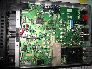
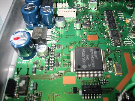
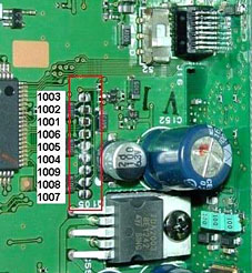
Locate the nine jumpers
about 2" from the front edge
of the main unit and about
3/4" from the left edge. For
144/430MHz expansion only,
remove the jumper at JP1002,
leaving the other jumpers
alone. For complete
expansion per the above
listing, place jumpers at
JP1007/1008/1009, and remove
the jumpers at
JP1001/1002/1003/1004/1005
(leave the jumper at JP1006
in place). NOTE THE
UNUSUAL SEQUENCE FOR THE
NUMBERING.
-
Replace the top panel; don't
forget to re-connect the
speaker lead removed in step
2.
-
With the transceiver off,
press and hold in the [F]
and [V/M] keys; while
holding them in, turn the
radio on. Modification is
now complete.
Hanno
Vogels, DG8JZ
Thanks
to
Roar Dehli
for this picture.
|
|
|
|
|
| Subject:
Jumper number |
User
comment |
|
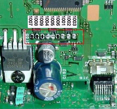
----BACK OF RADIO------
1007 - Jumper
1008 - Jumper
1009 - Jumper
1004 - Blank
1005 - Blank
1006 - Jumper
1001 - Blank
1002 - Blank
1003 - Blank
----FRONT OF RADIO-----
|
|
|
| |
| Installing The FT-857 Options |
|
|
| |
|
|
|
Author: -
pascal.34@bluewin.ch
Their is a second set of menu
functions
F01 to F74.
WARNING: changing these will
reset all
the memories.
I want to warn you do not change
these
values unless you are sure of what you are doing. To get
them turn
transceiver off. Press and hold the A,B,C keys; while
holding them
in, press and hold in the [PWR] switch for 1/2 second to
turn the
tranceiver On. Now let go of all keys. Attention, for menu
NO-017.
Input voltage 13.8V = 138 to calibre voltmeter.
Press F key to finish.
Function Setting in my radio
=============================================================
Adjust-No      Function            Setting  Mode    Frequency
=============================================================
NO-001         HF1-RXG             118        CW     1.800.00
NO-002         HF2-RXG             91         CW     7.068.19
NO-003         HF3-RXG             133        CW    21.225.13
NO-004         50M-RXG             106        CW    50.000.00
NO-005         VHF-RXG             77         CW   145.437.50
NO-006         UHF-RXG             103        CW   438.900.00
NO-007         SSB-S9              61         CW    21.225.13
NO-008         SSB-FS              54         CW    21.225.13
NO-009         FM-S1               68         FM   145.437.50
NO-010         FM-FS               99         FM   145.437.50
NO-011         DISC-L              50         FM   145.437.50
NO-012         DISC-H              79         FM   145.437.50
NO-013         FM-TH1              100        FM   145.437.50
NO-014         FM-TH2              100        FM   145.437.50
NO-015         FM-TI1              10         FM   145.437.50
NO-016         FM-TI2              10         FM   145.437.50
NO-017         VCC                 138        FM   145.437.50
NO-018         HF1-IC              83         CW     1.800.00
NO-019         HF2-IC              80         CW     7.068.19
NO-020         HF3-IC              87         CW    21.225.13
NO-021         50M-IC              84         CW    50.000.00
NO-022         VHF-IC              72         CW   145.437.50
NO-023         UHF-IC              74         CW   438.900.00
NO-024         HF1-PO-MAX          165        CW     1.800.00
NO-025         HF1-PO-MID2         105        CW     1.800.00
NO-026         HF1-PO-MID1         31         CW     1.800.00
NO-027         HF1-PO-MIN          13         CW     1.800.00
NO-028         HF2-PO-MAX          159        CW     7.068.19
NO-029         HF2-PO-MID2         102        CW     7.068.19
NO-030         HF2-PO-MID1         29         CW     7.068.19
NO-031         HF2-PO-MIN          11         CW     7.068.19
NO-032         HF3-PO-MAX          158        CW    21.225.13
NO-033         HF3-PO-MID2         101        CW    21.225.13
NO-034         HF3-PO-MID1         29         CW    21.225.13
NO-035         HF3-PO-MIN          11         CW    21.225.13
NO-036         50M-PO-MAX          145        CW    50.000.00
NO-037         50M-PO-MID2         92         CW    50.000.00
NO-038         50M-PO-MID1         47         CW    50.000.00
NO-039         50M-PO-MIN          8          CW    50.000.00
NO-040         VHF-PO-MAX          87         CW   145.437.50
NO-041         VHF-PO-MID          43         CW   145.437.50
NO-042         VHF-PO-MIN          7          CW   145.437.50
NO-043         UHF-PO-MAX          112        CW   438.900.00
NO-044         UHF-PO-MIN          16         CW   438.900.00
NO-045         HF1-TXG             48         USB    1.800.00
NO-046         HF2-TXG             38         USB    7.068.19
NO-047         HF3-TXG             43         USB   21.225.13
NO-048         50M-TXG             40         USB   50.000.00
NO-049         VHF-TXG             47         USB  145.437.50
NO-050         UHF-TXG             49         USB  438.900.00
NO-051         ALC1-M              203        USB   21.225.13
NO-052         ALC-M               85         USB   21.225.13
NO-053         HF1-REV-ALC         61         CW     1.800.00
NO-054         HF2-REV-ALC         56         CW     7.068.19
NO-055         HF3-REV-ALC         50         CW    21.225.13
NO-056         50M-REV-ALC         47         CW    50.000.00
NO-057         VHF-REV-ALC         62         CW   145.437.50
NO-058         UHF-REV-ALC         57         CW   438.900.00
NO-059         CW-CAR-LEVEL        144        CW    21.225.13
NO-060         AM-CAR-LEVEL        125        AM    21.225.13
NO-061         DEV-W               216        FM   145.437.50
NO-062         DEV-N               110        FM   145.437.50
NO-063         MOD-MTR             200        FM   145.437.50
NO-064         DTMF-DEV            10         FM   145.437.50
NO-065         CTCSS-DEV           233        FM   145.437.50
NO-066         DCS-DEV             168        FM   145.437.50
NO-067         LSB-CAR-POINT       -7         LSB   21.225.13
NO-068         USB-CAR-POINT       +5         USB   21.225.13
NO-069         VSWR2 at 10W        17         CW    14.257.90
NO-070         VSWR3 at 10W        42         CW    14.257.90
NO-071         ATAS-TEST                      LSB   14.257.90
NO-072         AMTR-TEST                      LSB   14.257.90
NO-073         HTEMP-THRESHOLD     38         LSB   14.257.90
NO-074         FTEMP-THRESHOLD     102        LSB   14.257.90
|
Hieronder staat diverse informatie over de
Yaesu FT-857D zendontvanger. |
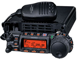
 Type: Amateur
HF/VHF/UHF transceiver
Type: Amateur
HF/VHF/UHF transceiver
Frequency
range:
- TX: 10-160 m + WARC / 6 m / 2 m / 70 cm
- RX: 0.1-76 / 108-174 / 420-512 MHz
Mode: AM/FM/SSB/CW
and WFM (RX only)
RF Power
output:
- 6-160 m: 100 W
- 2 m: 50 W
- 70 cm: 20 W
Sensitivity:
N/A
Selectivity:
N/A
Image
rejection: N/A
Voltage: 13.8
VDC
Current
drain:
- RX: 0.6-1 A
- TX: Max 22 A
Impedance: 50
ohms, 2*SO-239
Dimensions
(W*H*D): 155*52*233 mm
Weight: 2.1
Kg
Manufactured:
2003-2004
Other:
- Built-in keyer
- Beacon mode
- 32 color display
- CTCSS
- 200 memories
- Detachable front panel
- DSP option
Ultra Compact Design
Measuring just 6.1" x 2" x 9.2" (155 x 52 x
233 mm), the FT-857 is the worlds smallest
full-power HF/VHF/UHF multimode transceiver!
Its rugged case design is a masterpiece of
ergonomic design, with often-used switches
and knobs conveniently positioned for easy
access.
High-Performance Receiver Design
Building on the acclaimed performance of the
FT-1000D, Mark-V FT-1000MP, and FT-897,
Yaesus engineers have crafted the FT-857s
front end for a very low noise floor, along
with wide dynamic range. Utilizing an
up-conversion architecture for HF with a
first IF of 68.33 MHz, the FT-857 features a
double-conversion superheterodyne system
(triple conversion on FM), with the 2nd IF
at 10.7 MHz. Extensive bandpass filtering in
the front end, along with careful device
selection and gain distribution, yield a
receiver system ready for the strong-signal
challenges of todays crowded bands!
Wide Frequency Coverage
Providing transmitter coverage of the HF, 50
MHz, 144 MHz, and 430 MHz Amateur bands, the
FT-857 also includes receive coverage on 100
kHz to 56 MHz, 76 to 108 MHz, 118-164 MHz,
and 420-470 MHz. Enjoy the excitement of
public safety monitoring, along with weather
broadcasts, AM and FM broadcasts, aviation
communications, as well as the action on the
Ham bands!
Versatile Memory System
The FT-857 provides up to 200 "Main" memory
channels, each of which may be named with an
Alpha-Numeric label of up to eight
characters. These 200 Memories may be
separated into as many as 10 Memory Groups
of 20 Memories each. For added convenience,
you also get a "Quick Memory" and a "Home
Channel" on each band, plus ten pairs of
band-limit memories, to let you restrict
operation to a sub-band, if you like.
Digital Signal Processing (option)
For superior interference rejection and
transmitter "talk power," the FT-857s
optional DSP circuitry enhances both sides
of the communications circuit. The FT-857s
DSP Unit features a 24-bit high-tech D/A
chip for signal processing. Included are
Bandpass Filter, Auto-Notch, and Noise
Reduction filters, along with a Microphone
Equalizer.
Big Radio Tuning Dial and Outstanding
Ergonomics Ease of operation of the FT-857
is enhanced by the large-diameter (1.7")
Main Tuning Dial, similar in size to the
tuning knob of many base station rigs.
Selectable tuning steps of 2 kHz/4 kHz per
revolution allow easy navigation around your
favorite bands, while important keys and
switches are strategically placed around the
front panel for quick access.
|
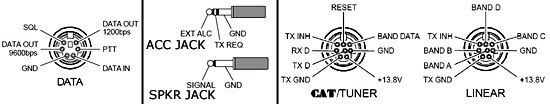
Pin Functies RJ45. Standaard zijn de
microfoon functies actief. Via Menu Mode No
059 [Mic Sel] is de modus in te stellen. Als
deze op [CAT] wordt gezet in plaats van [Mic]
kan deze poort gebruikt worden als data
interface.
Nr Mic Mode           Extra Functions
1  FAST               Power Switch
2  Ground (control)   PTT (Ground)
3  PTT                PTT
4  Mic AF             Mic AF
5  Ground (Mic)       Ground (Mic)
6  + 5V               + 5V
7  UP                 RXD
8  DOWN               TXD
|
|
By pressing both Band Buttons (UP & DWN)
while starting up, the FT-857 will beep a
few times and then displays the following
message: "RELAY CLEANING" and all the relays
start working. This is not mentioned on the
user or the service manuals. |
WARNING: Changing these will reset all the
memories. Aonly at your own risk!
IMPORTANT: Before changing any values in the
Aligment menue, please write down your
original settings!
WARNING: DOING THIS MOD MAY EVENTUALLY
RESULT IN A DAMAGED FINAL TRANSISTER AND/OR
REDUCED SERVICE LIFE!!
Enter the servicemenu. I want to warn you do
not change these values unless you are sure
of what you are doing. To get them turn
transceiver off. Press and hold the A,B,C
keys; while holding them in, press and hold
in the [PWR] switch for 1/2 second to turn
the tranceiver On. Now let go of all keys.
Press F key to finish.
For this procedure you will need a Dummy
Load (or a well matched Antenna) and a
Wattmeter!
Locate Menue No:
NO-024
HF1-PO-MAX 165 (set to 255) CW 1.800.00
NO-028
HF2-PO-MAX 159 (set to 255) CW 7.068.19
NO-032
HF3-PO-MAX 158 (set to 255) CW 21.225.13
NO-036
50M-PO-MAX 145 (set to 255) CW 50.000.00
NO-040
VHF-PO-MAX 87 (set to 255) CW 145.437.50
NO-043
UHF-PO-MAX 112 (set to 255) CW 438.900.00
Now you're done.
After this mod I have about 130 Watts on HF
and 6 mtr, about 90 Watts on VHF and 40
Watts on UHF!
|
|
40m Band Expansion (UK Version)
|
 I have expanded my radio frequency 7.100 to
7.200 mhz transmition using hardware jumper
fix method. This is how to do it:
I have expanded my radio frequency 7.100 to
7.200 mhz transmition using hardware jumper
fix method. This is how to do it:
Open the top
cover of the radio;
Locate the
jumper section- you will see nine jumpers
about 2" from the front edge of the main
unit and about 3/4" from the left edge;
Now remove
the jumper at JP1002 by using a low power
Soldering Iron (not to damage the board or
the next components);
Put
everything back and close the radio;
Press and
hold in the [F] and [V/M] keys and switch
the radio on while holding them.
|
Their is a second set of menu functions F01
to F74.
WARNING: changing these will reset all the
memories.
I want to warn you do not change these
values unless you are sure of what you are
doing. To get them turn transceiver off.
Press and hold the A,B,C keys; while holding
them in, press and hold in the [PWR] switch
for 1/2 second to turn the tranceiver On.
Now let go of all keys. Attention, for menu
NO-017. Input voltage 13.8V = 138 to calibre
voltmeter. Press F key to finish.
Function Setting in my radio:

Adjust-No      Function            Setting  Mode    Frequency
=============================================================
NO-001         HF1-RXG             118        CW     1.800.00
NO-002         HF2-RXG             91         CW     7.068.19
NO-003         HF3-RXG             133        CW    21.225.13
NO-004         50M-RXG             106        CW    50.000.00
NO-005         VHF-RXG             77         CW   145.437.50
NO-006         UHF-RXG             103        CW   438.900.00
NO-007         SSB-S9              61         CW    21.225.13
NO-008         SSB-FS              54         CW    21.225.13
NO-009         FM-S1               68         FM   145.437.50
NO-010         FM-FS               99         FM   145.437.50
NO-011         DISC-L              50         FM   145.437.50
NO-012         DISC-H              79         FM   145.437.50
NO-013         FM-TH1              100        FM   145.437.50
NO-014         FM-TH2              100        FM   145.437.50
NO-015         FM-TI1              10         FM   145.437.50
NO-016         FM-TI2              10         FM   145.437.50
NO-017         VCC                 138        FM   145.437.50
NO-018         HF1-IC              83         CW     1.800.00
NO-019         HF2-IC              80         CW     7.068.19
NO-020         HF3-IC              87         CW    21.225.13
NO-021         50M-IC              84         CW    50.000.00
NO-022         VHF-IC              72         CW   145.437.50
NO-023         UHF-IC              74         CW   438.900.00
NO-024         HF1-PO-MAX          165        CW     1.800.00
NO-025         HF1-PO-MID2         105        CW     1.800.00
NO-026         HF1-PO-MID1         31         CW     1.800.00
NO-027         HF1-PO-MIN          13         CW     1.800.00
NO-028         HF2-PO-MAX          159        CW     7.068.19
NO-029         HF2-PO-MID2         102        CW     7.068.19
NO-030         HF2-PO-MID1         29         CW     7.068.19
NO-031         HF2-PO-MIN          11         CW     7.068.19
NO-032         HF3-PO-MAX          158        CW    21.225.13
NO-033         HF3-PO-MID2         101        CW    21.225.13
NO-034         HF3-PO-MID1         29         CW    21.225.13
NO-035         HF3-PO-MIN          11         CW    21.225.13
NO-036         50M-PO-MAX          145        CW    50.000.00
NO-037         50M-PO-MID2         92         CW    50.000.00
NO-038         50M-PO-MID1         47         CW    50.000.00
NO-039         50M-PO-MIN          8          CW    50.000.00
NO-040         VHF-PO-MAX          87         CW   145.437.50
NO-041         VHF-PO-MID          43         CW   145.437.50
NO-042         VHF-PO-MIN          7          CW   145.437.50
NO-043         UHF-PO-MAX          112        CW   438.900.00
NO-044         UHF-PO-MIN          16         CW   438.900.00
NO-045         HF1-TXG             48         USB    1.800.00
NO-046         HF2-TXG             38         USB    7.068.19
NO-047         HF3-TXG             43         USB   21.225.13
NO-048         50M-TXG             40         USB   50.000.00
NO-049         VHF-TXG             47         USB  145.437.50
NO-050         UHF-TXG             49         USB  438.900.00
NO-051         ALC1-M              203        USB   21.225.13
NO-052         ALC-M               85         USB   21.225.13
NO-053         HF1-REV-ALC         61         CW     1.800.00
NO-054         HF2-REV-ALC         56         CW     7.068.19
NO-055         HF3-REV-ALC         50         CW    21.225.13
NO-056         50M-REV-ALC         47         CW    50.000.00
NO-057         VHF-REV-ALC         62         CW   145.437.50
NO-058         UHF-REV-ALC         57         CW   438.900.00
NO-059         CW-CAR-LEVEL        144        CW    21.225.13
NO-060         AM-CAR-LEVEL        125        AM    21.225.13
NO-061         DEV-W               216        FM   145.437.50
NO-062         DEV-N               110        FM   145.437.50
NO-063         MOD-MTR             200        FM   145.437.50
NO-064         DTMF-DEV            10         FM   145.437.50
NO-065         CTCSS-DEV           233        FM   145.437.50
NO-066         DCS-DEV             168        FM   145.437.50
NO-067         LSB-CAR-POINT       -7         LSB   21.225.13
NO-068         USB-CAR-POINT       +5         USB   21.225.13
NO-069         VSWR2 at 10W        17         CW    14.257.90
NO-070         VSWR3 at 10W        42         CW    14.257.90
NO-071         ATAS-TEST                      LSB   14.257.90
NO-072         AMTR-TEST                      LSB   14.257.90
NO-073         HTEMP-THRESHOLD     38         LSB   14.257.90
NO-074         FTEMP-THRESHOLD     102        LSB   14.257.90
|
|
Out of Band Mod (US Version) |
FT-857 modification for TX: 1.8-56MHz,
137-164MHz, 420-470MHz
Remove the
seven screws affixing the top panel of the
transceiver, and gently lift it upward.
Carefully
remove the small 2-pin speaker plug from the
left rear corner of the transceiver interior
then remove the top case and set it aside
for the moment.
Locate the
nine jumpers about 2" from the front edge of
the main unit and about 3/4" from the left
edge. For 144/430MHz expansion only, remove
the jumper at JP1002, leaving the other
jumpers alone. For complete expansion per
the above listing, place jumpers at
JP1007/1008/1009, and remove the jumpers at
JP1001/1002/1003/1004/1005 (leave the jumper
at JP1006 in place). NOTE THE UNUSUAL
SEQUENCE FOR THE NUMBERING.
Replace the
top panel; don't forget to re-connect the
speaker lead removed in step 2.
With the
transceiver off, press and hold in the [F]
and [V/M] keys; while holding them in, turn
the radio on. Modification is now complete.
|
|
There is written a small program to update
the Jumper settings for the Yaesu FT897,
FT817 and FT857 via the CAT interface! It is
available on http://www.ham.dmz.ro -
softjump.zip This program allows you to
perform the jumper modification without
modifying the hardware on your radio!
|
|
Feedbackdistortion Solution |
|
The only real problem I have encountered
with the radio was the feedbackdistortion
problem mentioned in other messages here but
one call to the Yaesu technicians cured it.
They advised me to roll up a few turns of
the coax in a 6 inch (15,24 cm) loop at the
transmitter to kill the RF. It worked like a
champ. I think the DTMF remote mic could use
some more shielding as there was no problem
at all using the stock mic. But the coax
coil is something I would reccommend to all
mobile users anyway. |
|
Adding drag to the tuning knob |
The tuning knob on the FT-857 free wheels
too easily. If you prefer a tighter knob
with more drag, here is what to do per a
Vertex Standard Technicion. Remove the
rubber ring around the big tuning knob.
Using an allen wrench, loosen the allen
screw and remove the knob off it's shaft.
On the shaft you will now see a steel
spring. This spring can either add tension
or loosen the tension on the knob's shaft.
To add more drag just tighten the spring's
tension on the shaft. Do the opposite for
making less tension on the knob. After you
adjust to your likes, put the knob back on,
tighten the allen screw, and put back on the
rubber ring on knob. |
Dear reader, Being one of Belgium's primary
repeater keepers, I put a lot of stress and
attention on having correct deviation on my
systems, and I keep on telling people to
adjust (=decrease) their deviation.
Everybody using the latest generation of
kenwood rigs is being shouted at for a far
overdriven deviation. The standard is 3kHz,
and most manufacturers keep on selling WFM
radios producing over 5 kHz. Unfortunately,
my recent birthday present, the FT-857,
apart from having a very weak HF-frontend,
is proud of producing an overdeviation on
FM. It is not possible getting the rig to
become a decent performer in the 12,5 kHz
european world only using the FM mic menus,
so here is the solution:
Press A B C
simultaniously when powering onuropean FM
Settings;
Select
(rotary button) item 061 DEV-W and adjust
(dial) for 125 (=3 kHz deviation);
Select item
062 DEV-N and adjust for 50 (=1.5 kHz
deviation);
Select item
065 CTCSS-DEV and adjust for 160 (=500 Hz
deviation);
Press
Function to exit;
Adjust FM MIC
Gain in the menu for 15 (was 50 default) and
now you are ready to start on FM without
ruining the adjacent channels.
Thanks for your cooperation keeping the
spectrum clean (and narrow).
|
|
Low Frequency Response in SSB |
You can add low frequency responses in both
transmit audio as well as receive audio in
SSB mode. Basically you shift the carrier
point in relation to the audio passband. You
can change these values this way:
Push the function key until the menu
appears. Now go to the following menu: (note
that default all four values are set to 0
Hz) CAR LSB R (menu 15). Here you can adjust
the LSB reception carrier and effectively at
+300 Hz pull down the audio band pass down
to 100 Hz. Same story for CAR LSB T (menu
16) - this is for the transmit part. Again
same story for menu 17 and 18, for receiving
and transmittin gon USB. Note that for the
USB part, you'll have to shift the other way
-- e.g. if LSB is at +250, the USB should be
at -250. |
|
|
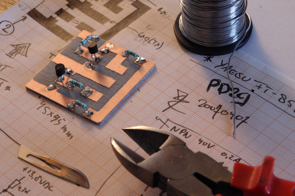
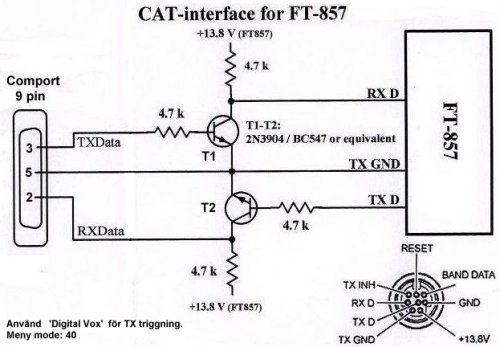
Aan de hand
van deze tekeningen heb ik een kabel gebouwd.
Echter werkt deze niet. Als vervolg heb ik
ook de variant gebouwd met een IC. Echter
werkt deze ook niet. Ondanks dat het zeer
zorgvuldig is uitgevoerd werkt het systeem
niet. Aangezien de set een duur apparaat is
heb ik besloten om een originele CT-62 kabel
te kopen. Door het uitgeven van € 35,00 loop
ik in ieder geval niet het risico om de set
of computer te vernielen.
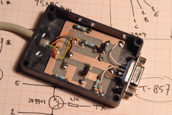
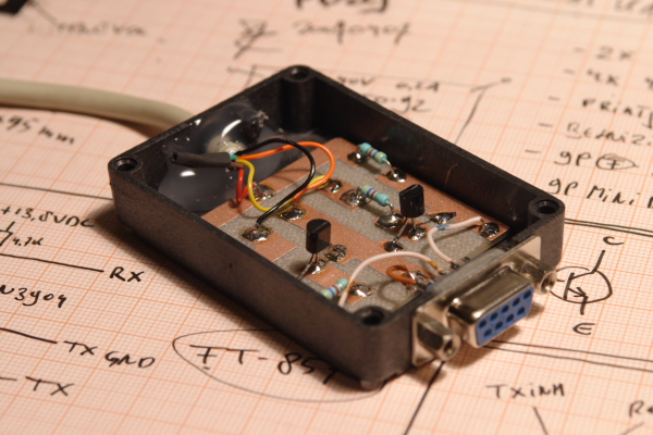
Uiteraard heb ik even in de kabel gekeken om
te zien wat er in zit. Echter is gebleken
dat de interne schakeling ingewikkelder is
dan de schemas welke op het web te vinden
zijn.
Dus alle doe-het-zelf kabels zijn zeker niet
zo goed als de originele. Dit is geen
reclame verhaal. Ik vind het bedrag érg hoog
voor een stuk kabel, dus wilde ik eerst een
goedkopere kabel hebben door deze zelf te
maken. Echter ben ik nu duurder uit. Mijn
advies is dus ook om meteen een goede
originele kabel te kopen. Dan ben je
vooralsnog voordeliger uit en dan loop je
geen risico om iets te vernielen.
Mijn advies is dus om deze schemas niet te
gebruiken! |
|
|
|
|
|
|
|
|
 KB2LJJ