Last updated 25/6/2024
Get:
https://groups.io/g/AusLMRadio/files/Philips%20FM900/fpp.exe
Run this self extracting FPP.EXE using "wine" then copy
to "dosbox" c:\FPP as it is a DOS program and HAS to be on C:\FPP !
Before "F10 NEXT" when the No EPROM programmer found" appears,
Use SAVE to generate a .BIN file for your eprom programmer.
Find the .BIN file in JOBS\jobFile\
If you are running DOSBOX only, get my fpp3 zip file here:
First updated 27/10/1999
If this is not your first visit here, please push your refresh button!!!
After much searching on the 'net I
have found a few places with FM900 info on them, however they
take a lot of jumping from one site to another to find everything
you are looking for. So with many apologies to all concerned (I
will list as many of the sites as I can at the bottom of the
page) here is a compilation of all the best parts, images, eprom
binaries etc... that i have collected. I personaly have a W1 band
FM92R and a W1 Band FM91, so most of the information I have
collected is biased towards these models. Also I am being sent
the FULL service manual for the FM91, each page is scanned and
saved in .TIFF format and I will make this available here as it
arrives. All files will be less than 1 Meg in size, both for
download speed and the fact that is the maximum file size on this
server!!
BTW....Don't think we here in Australia are alone with these
wonderful beasts, I received e-mail from Jan
Buiting PE1CSI from Sibbe
in The Netherlands about an FM913 on 2M and an FM906.
For those considering purchasing an
Phillips FM900 series radio, and are confused by the band codes
used, the band plan is as follows:
E Band radios are Lo Band VHF covering 68-88 MHZ:
This is the one to convert to 6M
B Band radios are Hi Band VHF covering 132-153
MHZ: These are fine for 2M amateur
A Band radios are Hi Band VHF covering 148-174 MHZ
T Band radios are UHF covering 403-420 Mhz
U Band radios are UHF covering 440-470 Mhz
W1 Band radios are UHF covering 470-500 Mhz: These
are the ones for UHF CB use
W2 Band radios are UHF covering 500-520 Mhz
The 8 Pin microphone socket pin-out is as follows:
For those who wish to scan (or use tone mute) and do not have a magnetic microphone clip, a simple modification is as follows. Open your standard fist mic, locate the steel strenghtening plate at the rear which supports the mic hanger clip, and clean the coating from a small portion of it, (I scraped mine with a screwdriver 'till it was shiny). Then solder a short length of wire to this point, and solder the other end to the pin where the blue wire joins the pc-board. Then all you have to do is to run a ground wire from your radio, or the power supply running the radio, to your standard mic clip. All the reed switch/magnet combo do is to short the blue (cradle) wire to ground, so this is just another way of doing the same job.
This one came through the FM900
Mailing list, a word document describing one way to have 4 banks
of frequencies stored in the the one eprom and how to switch
between them Click here!
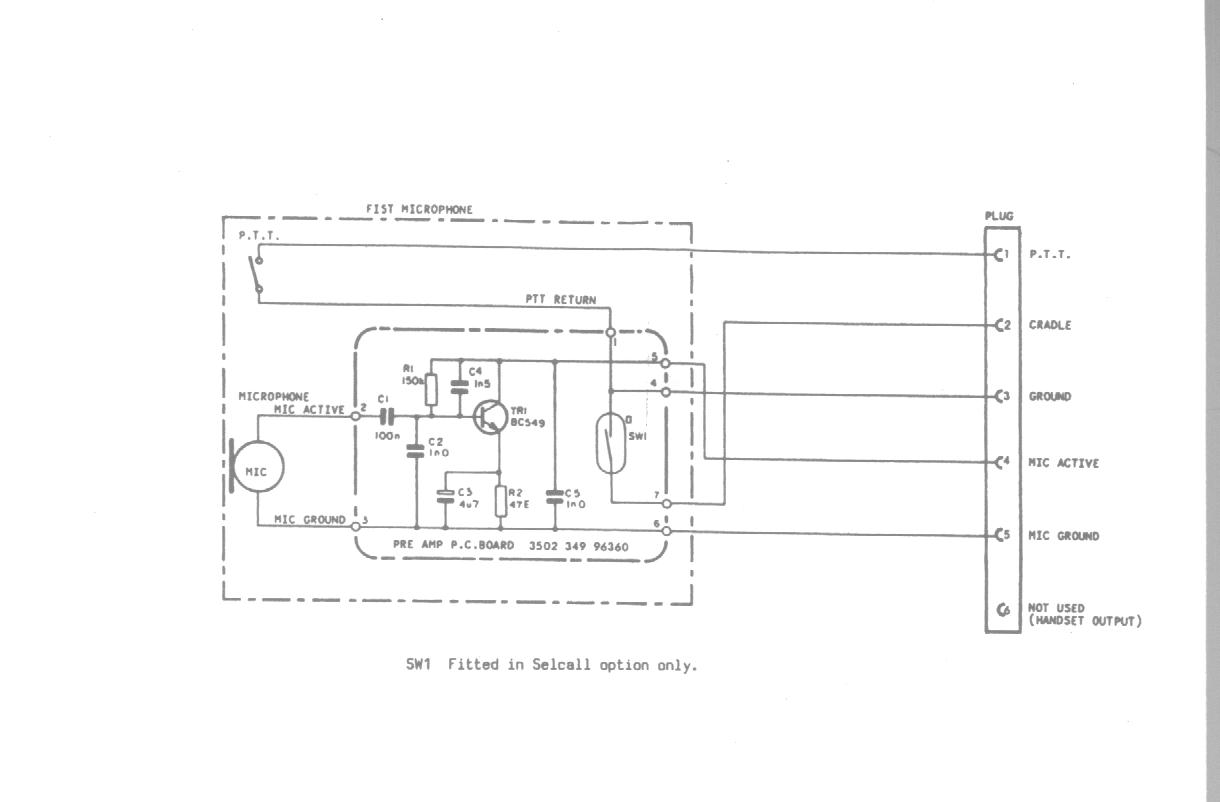
Another offering from the FM900 Mailing list is a couple of
schematics, the microphone preamp and associated wiring, and also the
8pin and 5pin sockets
on the base unit.
Why not subscribe to the FM900 Mailing list, a source of
heaps of usefull information and others interested in these fine
radios.
In the early eighties, Philips Australia started producing a
commercial radio for the Australian and international markets.
The radios came in various configurations and frequency bands.
They where constructed from a one piece die-cast enclosure, with
ether a local control face plate or remote control head. The
circuitry is contained on 3 main boards (RF, CPU and PA),
PCB's are double sided FRG4 fibreglass. All of the components are
through hole except the SMT parts mounted on ceramic hybrid
SIP's. The whole construction is extremely ruggedised and very
solid. The FM900 series came in 3 basic models (FM91, FM92 and
FM93). It also came in some special/custom variants and also a
waterproof model FM97.
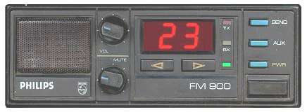
The FM91 is intended as the high end 120 channel model and only
came in a remote head version. It has a numeric keypad, function,
scan, site, send keys, digital mute and volume, it also has an
eight digit seven segment red LED display, most options are
programmable from the head.
The FM92 was the standard 40 channel radio (up to 99 CH's), it
came in 2 variants, local head and remote head. It has channel
up/down, aux and send buttons, analog mute and volume. The
display consists of two seven segment red LED display. The radio
can be programmed with almost the same options as the FM91 but
it's not changeable from the front panel. The remote head also
has a built in speaker. This is the most common FM900 series
radio.
The FM93 is the low end 10 channel baby. It has channel up, aux
and send buttons, analog mute and volume. The display is a single
seven segment green LED display. It only came in a local head
version and differs considerably from the other FM900 series
radios, in that it's a servery striped down version, utilising
cheaper receiver section and different PLL. It also lacks an A-D
chip, therefore it can't facilitate some functions, mainly
voting. Sometimes these units actually have FM92 PCB's installed,
but they can only display channels 0-9.
The FM97 is basically a waterproof FM92 with an FM91 CPU board.
It only came in a remote version, the head was made from a white
die-cast jiffy box, it uses Mil-spec bayonet connectors and high
quality push button switches with waterproof boots. It has volume
up/down, channel up/down, mute, a, b, c function buttons. The
display consists of 4, 7 segment red LED displays. According to
information from an ex-phillips employee they were designed for
police motor bikes!!
The only real deference between the FM91 / FM97 and FM92 is that
the FM92 has a standard volume control pot, but the FM91 / FM97
has a 4 bit digital audio attenuator hybrid instead.
All models are based on the Motorola MC146805 CMOS micro
controller, and normally have an 8k (2764) EPROM. The EPROM
contains the program code and channel data.
All models have provisions for add on modules or
"options" as Philips calls them.
The much asked for E band to 6M amateur conversion is HERE!!! This is scanned images from the AR magazine
articles and also the 6 Meter Eprom image files for both local
and remote radios.
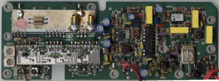
Here is an image of the receiver board, showing the resistor to
cut to attenuate (by about 95%) the channel change beep and off
cradle scan alarm tone. Click here
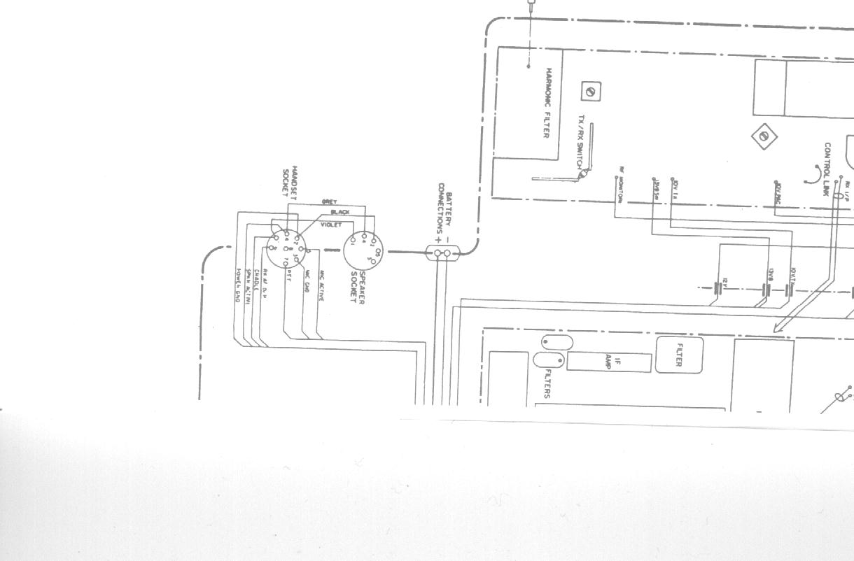
Here is the 5 pin speaker socket pinout (also works for the
socket on the rear of the remote head) Click here
This is a picture of the UW FM90 Duplex Board Module Here
Here is the image of the synthesiser board Click here
This is the pinout for the "umbilical" cable that
connects the remote head to the main body Click here
Here is a variable gain (hi/lo) receive preamp for both the VHF
and UHF radios Click here This is really SMALL!!!, it is built on a
piece of vero-board 12 holes by 5 holes!!!
Here is the Field Personality Programmer for download (FPP.EXE is
a self extracting zip) Click here This file also includes the updated FM93
Master file for those having trouble programming these radios.
NOTE: This creates the binary images for any eprom programmer to
work with, the one used in the software is an add-on card
available only from Phillips/Simico, the files created work fine
with the eprom programmer listed below.
This is a
copy of Pascal's S-Meter for FM900 Page I have built one and it is great!!!
This is a great "do it yourself" parallel port eprom programmer to "burn" your own eproms from
FPP image files.
For those who want just the image files for UHF CB, here they are
for:
FM92 Remote
Head
FM92 Local
The
Channel Allocations for the above files
Here is a link to David Griffiths' AFI900 Software Site , a very nice extended re-programming of
the eprom, adds HEAPS of cool features, I love the scanning
options.
The circuit diagrams are BIG (1.85Meg), I have used arj.exe
(version 2.41)to split them into "sub 1Meg" blocks, to
comply with this servers limits, use the command arj x -v
"filename".arj to re-create it as one picture.
This is the first of the pics, Fig 7.13 Part 1 Part 2
Part 3 YOU MUST GET ALL THE PARTS OR IT WON'T
WORK!
Here is Fig 7.2 Part 1
Part 2 Part 3
YOU MUST GET ALL THE PARTS OR IT WON'T WORK!
Here is another one, Fig 7.1
(It has 3 in it, a,b,c)
List
of blank pages not included in files (so you don't panic when printing it all
out!!)
Part
1 of the FM91 Service Manual
Part 2
of the FM91 Service Manual
Part 3
of the FM91 Service Manual
Part 4
of the FM91 Service Manual
Part 5
of the FM91 Service Manual
Part 6
of the FM91 Service Manual
Part 7
of the FM91 Service Manual
Part 8 is the diagrams mentioned above!!
Part 9
of the FM91 Service Manual
Part 10
of the FM91 Service Manual
Part 11
of the FM91 Service Manual
Part 12
of the FM91 Service Manual
Part 13
of the FM91 Service Manual
Part
14 of the FM91 Service Manual
S-Meter Circuit courtesy of Pascal,
VK2IHL
Gifs and mic wiring courtesy of Michael,
VK2XMD
E Band to 6m conversion courtesy of Northern
Corridor Radio Group (WA)
Eprom Programmer courtesy of Andrew
McCubbin
FM91 Service Manual courtesy of Kevin
Forbes, Capt Nimrod
The really nice pic at the top of the page is courtesy of David Griffith
The Information about the FM900 Series was taken from Here
The pre-amp came from the same source, Ash
The Duplex Board piccy came from Andrew
Dennis
Comments/Corrections
to Chris Hogan
