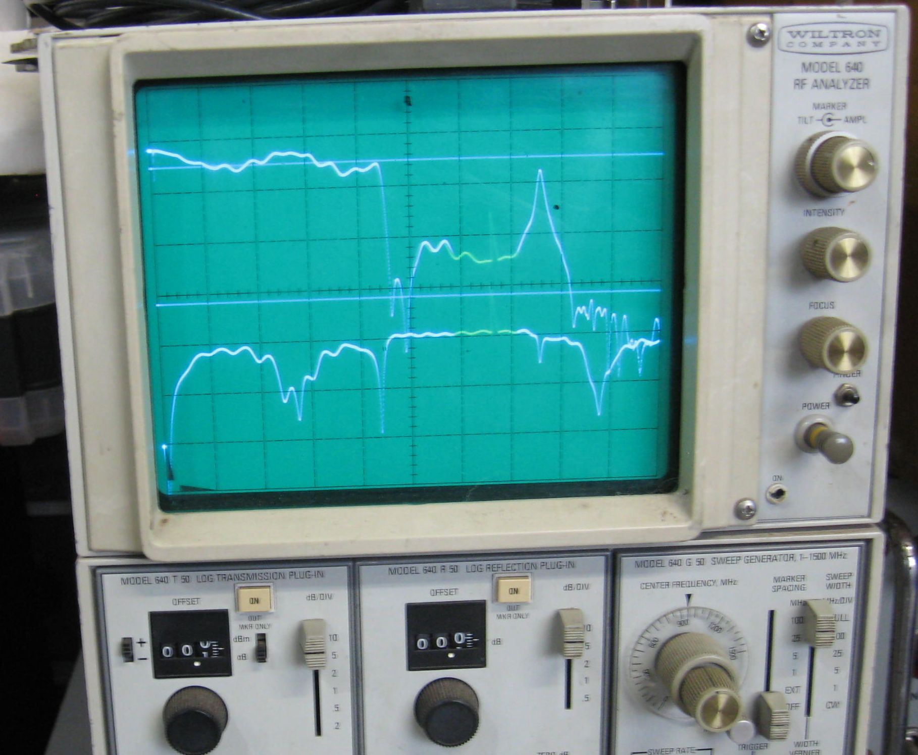
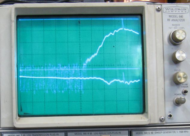
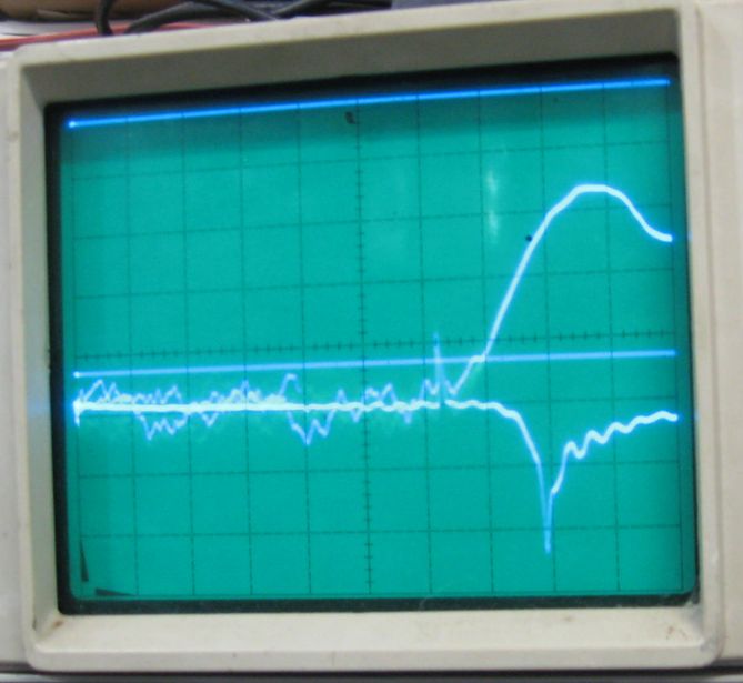
0 - 1500MHz. Top trace: coupling to second port
Bottom trace: Return loss, Frequency of interest, where that dip is at about 1300 MHz.
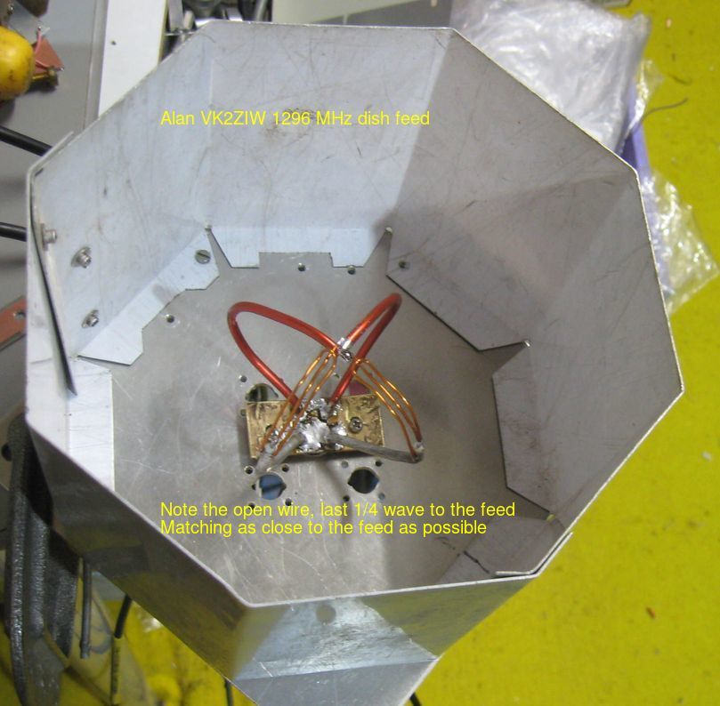
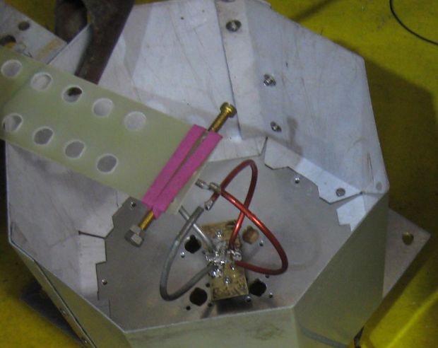
Feed under the groundplane.
1/2 wave on one side of the BNC connector, full wave the other.
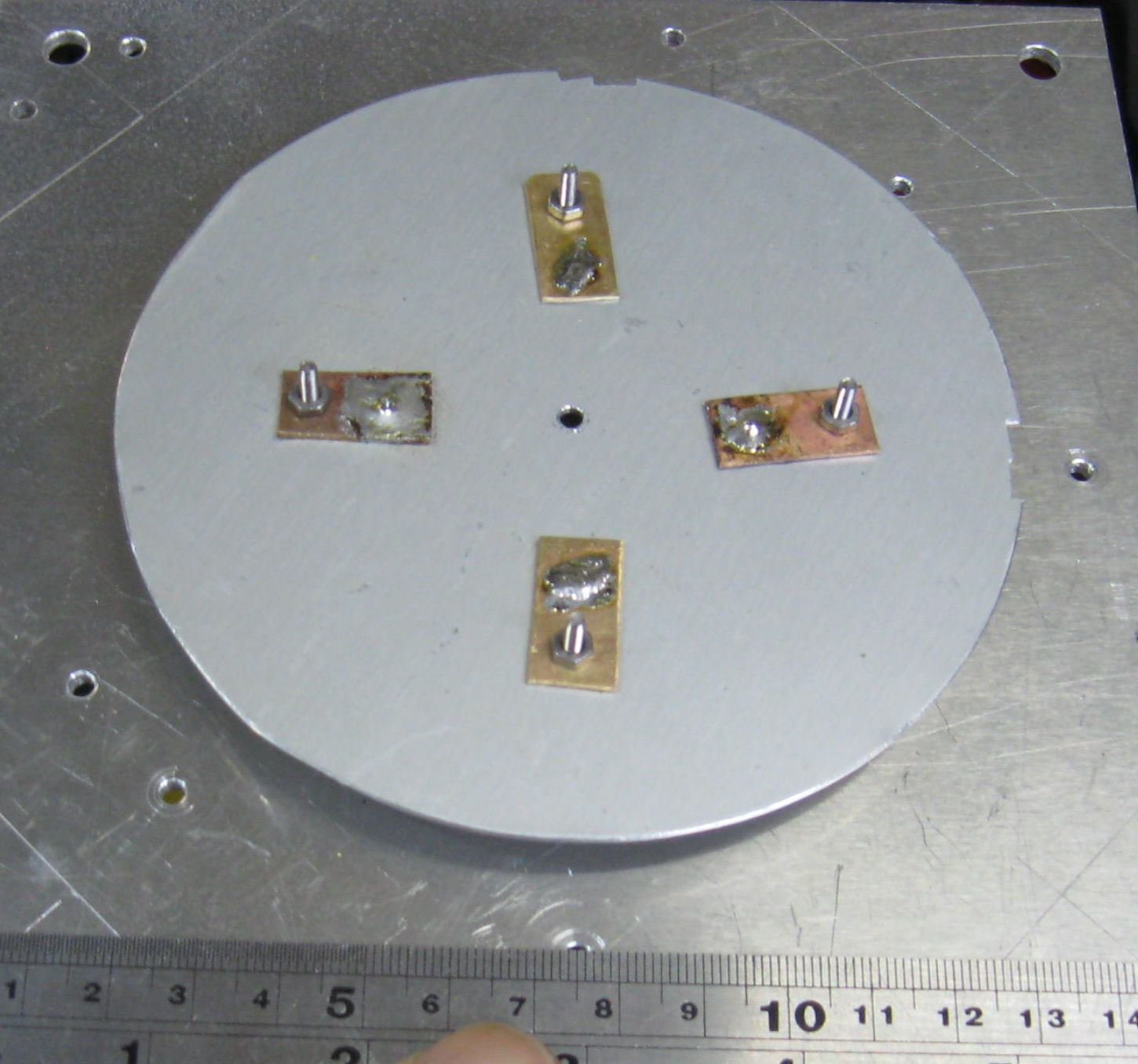
Top view of the patch. 119mm dia.
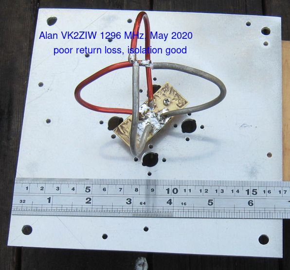
Built with available materials.
Just backyard tools, some aluminium, brass sheet, coax and a soldering iron.
To test a theory.
For EME (Earth Moon Earth) we rely on the fact
that a circular polarised signal when reflected off an object,
the sense of the circular polarisation is reversed.
Waveguide septum polarisers are practial on 1296MHz (23cm wavelength) and up but down at 432MHz are too big.
Here is an alternate feed.
Is this antenna useful? I think "no" too narrow bandwidth.
I made a second patch to get closer to frequency, 2mm larger and cut the former down 2mm and tried it on top
to perhaps get broader bandwidth.
Did it work, no! Killed the Return loss, everything.
I was following from a Google search "patch antenna balanced feed":
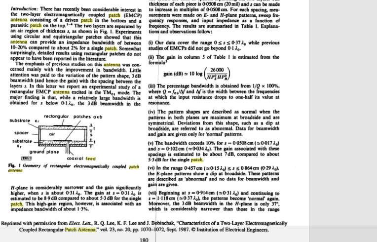
and
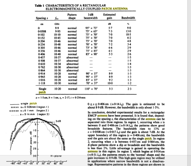
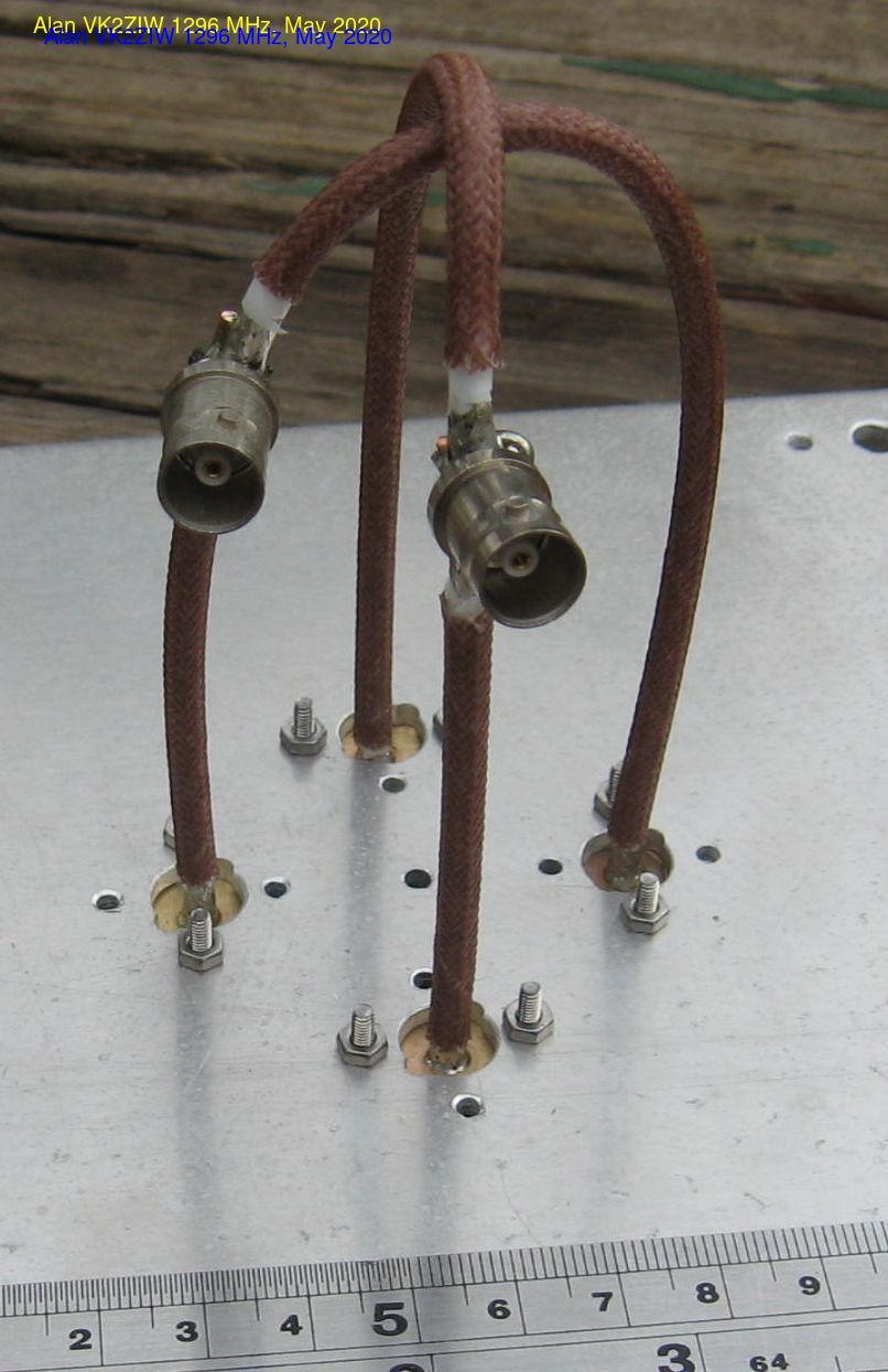
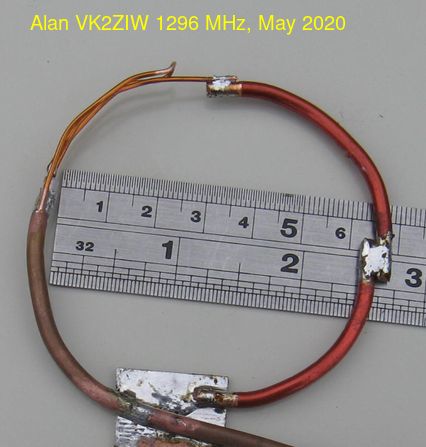
Using the base hardware, what about loops?
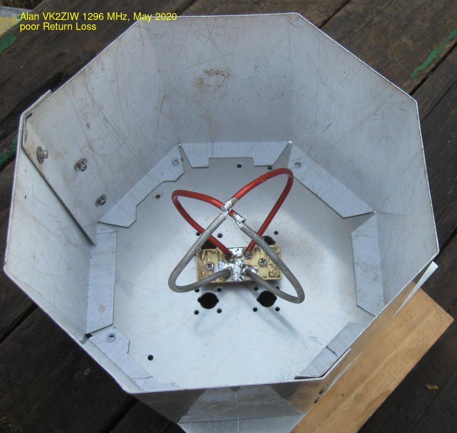
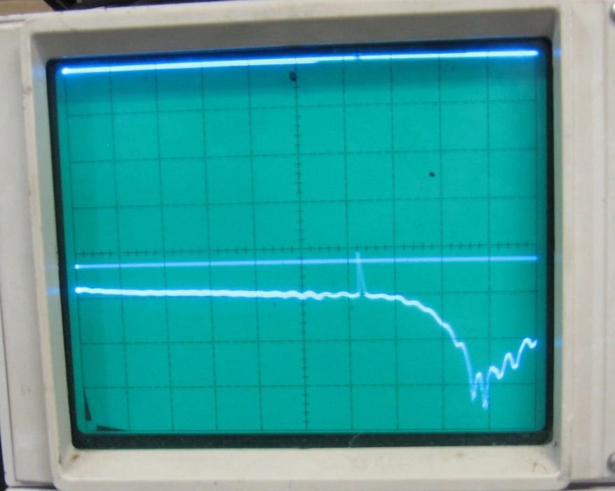
Sweep from 0 to 1500 MHz, Similar loop for the RF input, 500mm away.
Definitely radiating, lower trace shows very poor Return Loss.
This above is the basic feed system, the easy to make loop.
This is about what can be done without a lot of care.
Actually, I didn't take much care, wrapped the loops around my coffee cup.
Actually this about finding what can be done without a lot of care.
Now to make it useful.
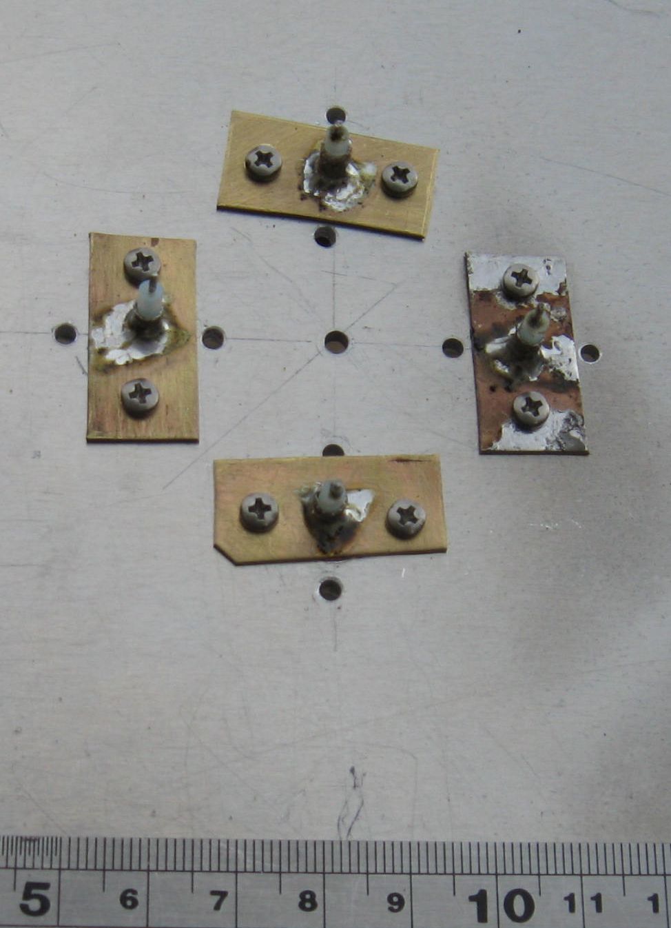
Not just any screw, a brass three inch 2BA. Not at optimum position, close.
Much better Return Loss. And tunable by length and position.
Now to test the isolation between the loops.
Actually better than 25db.
Now to make a perspex sheet to keep the birds out and to mount that screw.
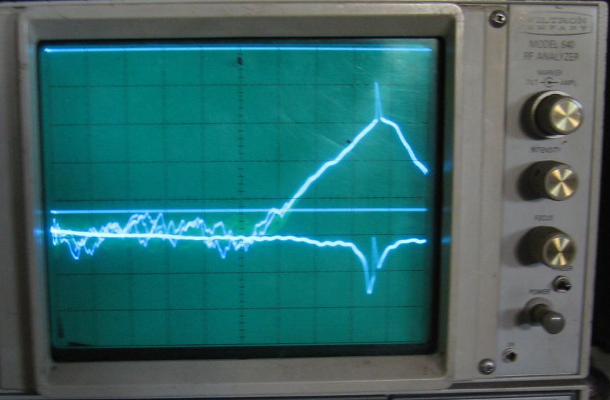
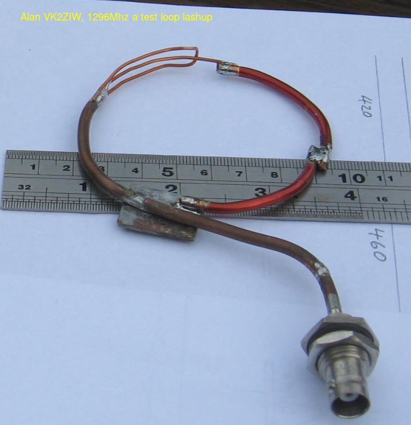
A bedtime inspiration, the open wire 1/4 wave of higher impedance.
Look at that great Return Loss and reasonable bandwidth.
0 to 1500 MHz, 1mm wire, grounds spaced about 6mm. Was this luck??
Same loop in the cup. Still reasonable match, broad band.
Best match shifted down 100 MHz
Ready for testing with the hybrid.