1st consideration, as few elements as possible
2nd, simple feed
3rd, No reflector needed
The ZL Special depends on two dipoles spaced 1/8 wavelength, fed 135 deg out of phase.
The feedline is actually 1/8 wavelength long and twisted 180 deg.
If I can get the feed impedance to be 100 ohm, by making the element a little shorter and putting an inductor (or stub) across the dipole feedpoint, then, both dipoles in parallel, will make the main feedpoint 50 ohms - magic, perfect SWR.
100 ohm balanced feedline, isn't that the four twisted pairs in CAT5 cable?
I have 50+ meters of teflon wire, pink, 1.3mm OD, 1mm silver plated stranded wire, obtained in the 70s. Twisted, perfect for the job.
I twisted two 81cm pieces and measured a 70MHz dip.
Thus my feedline is about 80% velocity factor, so it is not long enough to go directly between the driven elements. I simply feed the driven elements somewhere between them such that the difference in length between the two feed line lengths is the required 1/8 wavelength.
Well, I built the antenna, copied the design from a 2m design, multiplied all dimentions by 2.9 (145 / 50 = 2.9), 1/2in aluminium tube, 2x1in L boom with 1/4in x 2in x 7in PVC element supports.
Elements, tip to tip, D1 2820mm, stubb 330mm 60mm wide, D2 2708mm, both 20mm gap at inner ends, Director 2670mm. Element apacing, D1 to D2 736mm, to Director 957mm. Coil across D2 feed 4T 1/2in ID 1mm wire. Connection to driven elements, 20mm x 4mm self tapper screws, then solder to screw heads.
Feed system, 1/8 wavelength is 57cm, so, I cut two pieces of twisted pair, 77cm to D1, 20cm to D2 twisted 20mm/turn. Both pieces are a little long so go through a ferrite bead 16mm dia, 8mm ID, 16mm long(this is the balun), then soldered, in parallel to a BNC socket, fixed to the boom. I marked the wire ends and soldered the feeds onto driven elements, long one to the rear, phases swapped.
Soldering to aluminium. Don't. Just put a stainless self tapper screw through the aluminium tube and solder to the screw head.
Actually, it can be done, under oil. I use automatic transmission oil. First, drill holes through and close to the element end to reduce heat loss up the pipe. File the surface, under oil. I use lead free solder. Once tinned, 'tis easy.
Results: 2MHz bandwidth centred on 49MHz, SWR better than 1.3:1, excellent front to back.
I was surprised at the bandwidth.
Design notes, with 20db front-to-back, no reflector is needed (One less element). Relativly wide spaced means lower Q, hense wider bandwidth.
Tuning, the stub could have a slider bar, or, a freestanding air coil can be expanded or squeezed and still be very robust. Changing element lengths, forget it.
Comments by L. B. Cebik, W4RNL
element 2710mm tip to tip, easy to adjust coil
element 2820mm tip to tip, hairpin 320mm with adjuster
Noting that the feed impedances are low, how about series-ing up the feeds to get our magic 50 ohm. Paralleled 50 ohm line gives 25 ohm line. Then seriesed, back to 50 ohm.
Also, seriesing the elements forces the current match to 1:1, any comments?
All spacing 750, Dir1 2835, Dir2 2825, Driven both 2880 (mm)
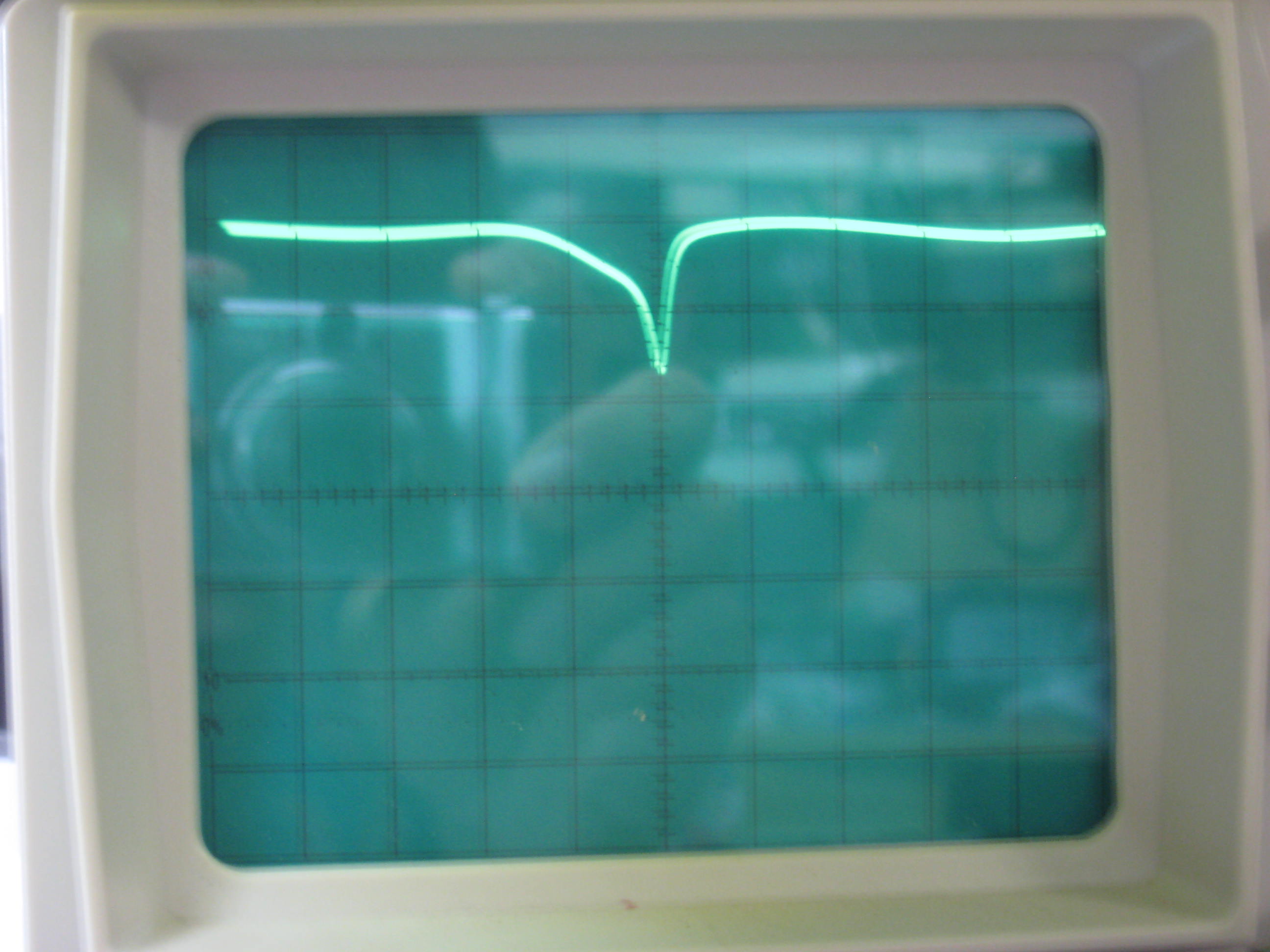
Note narrow bandwidth 1MHz/cm. At first, the fed elements were the origional 3000mm
but the dip on the left was 2.5MHz lower in frequency, so were shortened 120mm.
The sharp dip did not move after the 120mm was cut off.
The proximity of an element, resonant in the band, makes quite a difference
to the impedance of a driven element, as seen in this sweep.
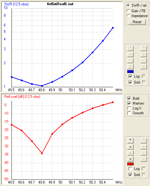
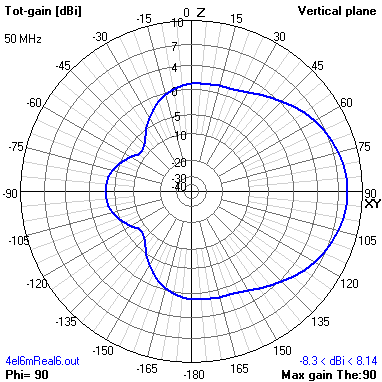
Simulation with 4nec2, twin coaxes paralleled, hense 12.5 ohm F/B is not that good realy barely 10db
I fiddled and faddled but with 4 elements, a 'normal' 4el would be better then take a look at this:
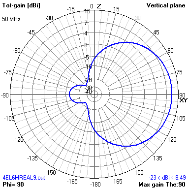
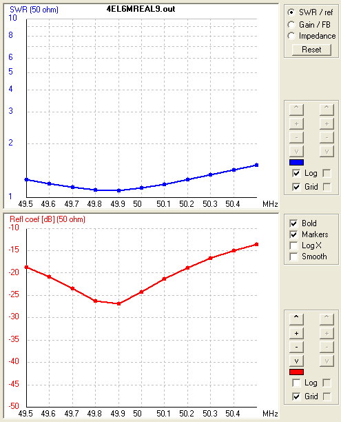
4nec2 .4el6mReal9.nec. Tricks: Matching included (1/4wave 25 ohm line) and, less feed to rear ZL element
It pays to simulate the lot.
Include the matching in 4nec2. Tansmission line matching is easy to add and adjust, just impedance and length.
In a ZL beam, the power to the rear element has to be less. This can be adjusted by the feedline impedance to it. 25, 35, 50, 75, 100 are useable.
4nec2, Be careful with, maximise gain. When element lengths get too close to critical length, everything goes haywire.
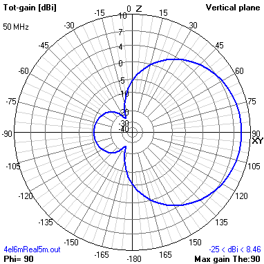
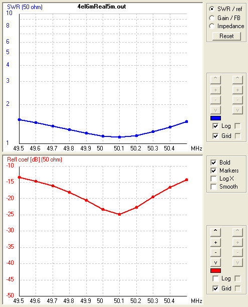
4nec2 .4el6mReal5m.nec. Tricks: Matching included (25 ohm line) and, less feed to rear ZL element with 100 ohm line
10 Jan 2014 This is now on the tower and WORKS. No tuning. Best SWR is exactly on 50.0MHz.
Back to conventional 4el with paralleled 70 ohm coax matching.
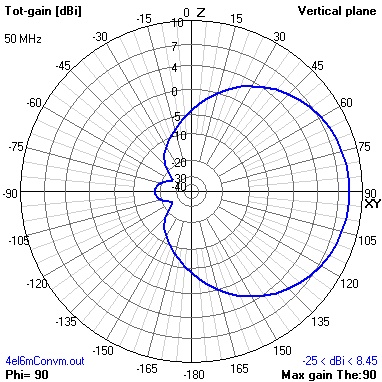
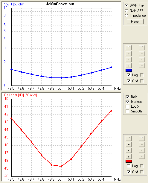
4nec2 .4el6mConvm.nec. Even spaced. Matching included (1m of 35 ohm line). Conventional reflector. Not quite as good F/B.
Conclusion: ZL feed of no significant benefit. All that is of note, with ZL, the F/B pattern stays constant over a WIDE range.
Conclusion 2: Matching, short paralleled coax with a torroid over it, is super. Why do anything else.
Email me if you have read this vk2ziw (a) this url, unixservice... com.au