These are images from a 2012 UK presentation by Dave Mann G8ADM:
https://www.youtube.com/watch?v=ZeNan5_Dbrk

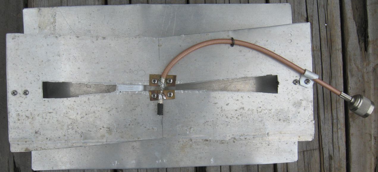
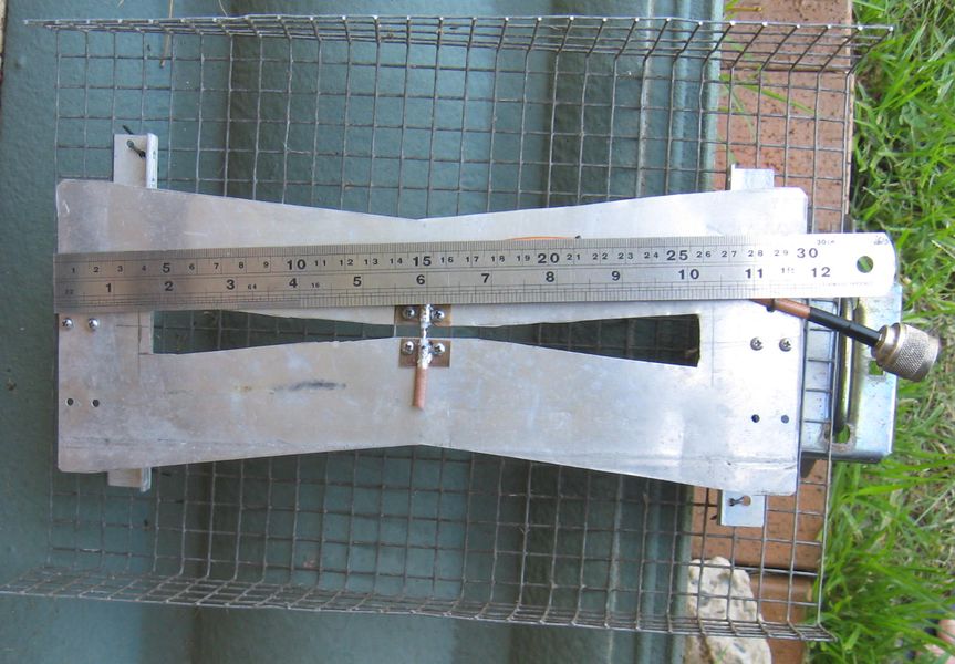
So I 'had a go' for 23cm, the front sheet 300mm x 120mm and the reflector 300mm x 118mm
Slot 6mm and reflector spaced 60mm back
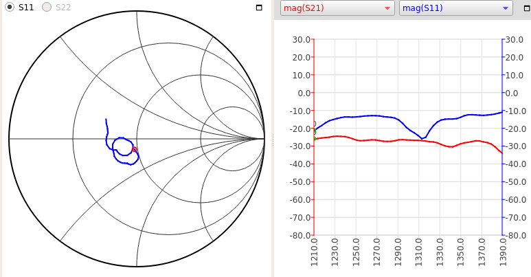
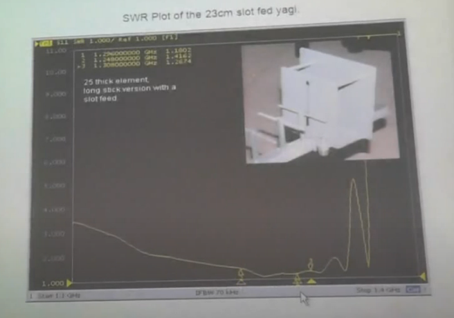
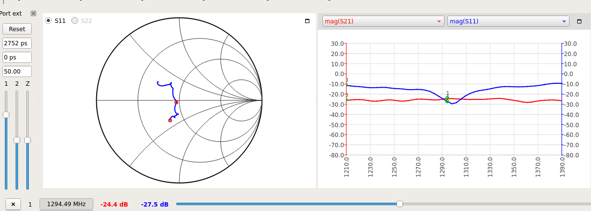
The SAAv2 plot showning in in blue the Return Loss
and in red, the signal received by a Vivaldi 1m above
Gain:, it looks like two 2el beams stacked 1/2 wavelength apart, so ~8dbd.
Moving it around and observing with the Vivaldi, definitely has gain.
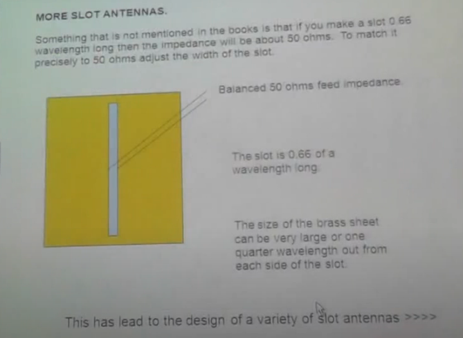
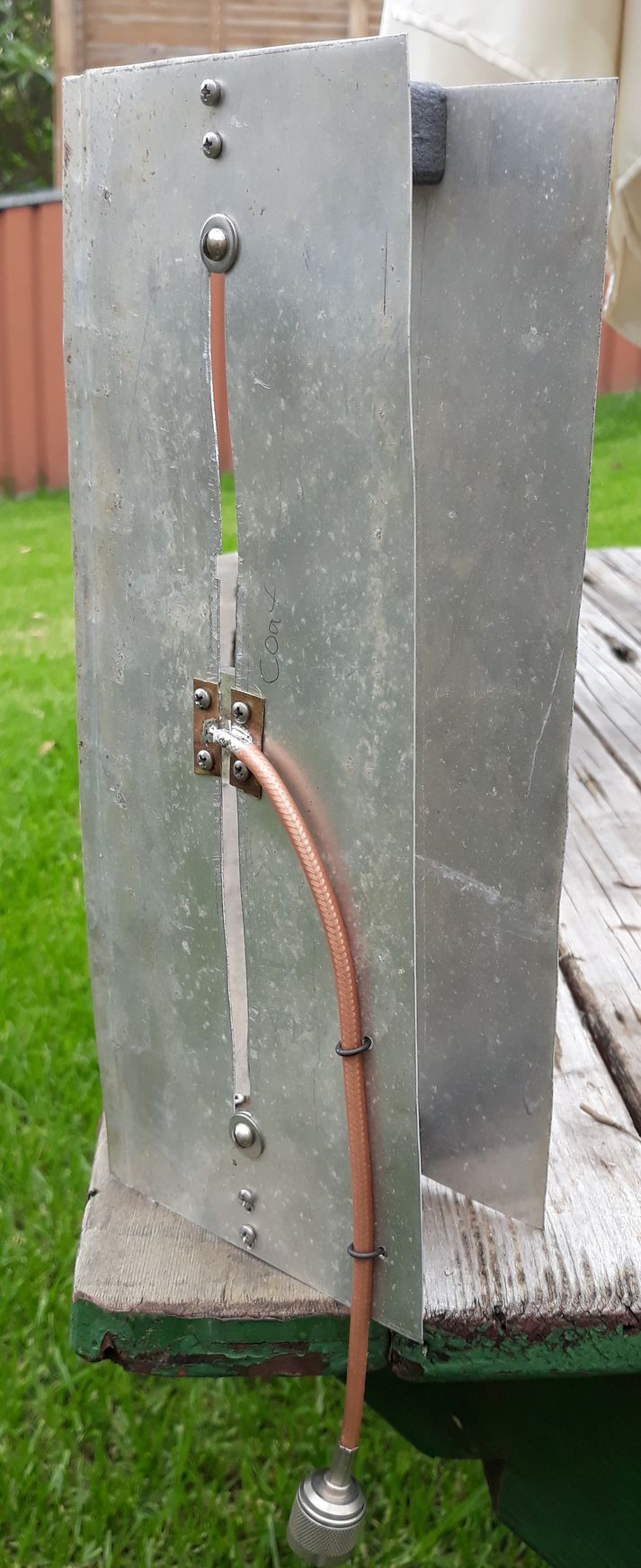
In the UK 2012 presentation, the author made his elements in brass and mentioned,
aluminium cannot be soldered too. Well, small brass plates as you see in my construction
have such a large capacitance to the metal below, problem solved. There's a perspex block
behind 'rigidising' the centre area of the slot.
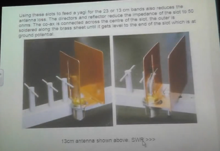
After some work: Note the feed coax comes out at the centre, NOT TO ONE SIDE!
I'm tempted to make a much larger reflector sheet.
Touching the corners with ones fingers, they are 'hot' much more so than the edge centre.
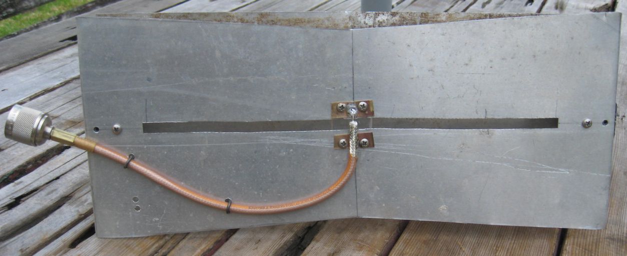
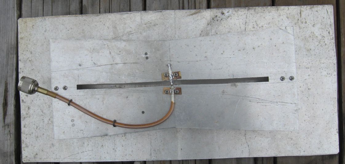
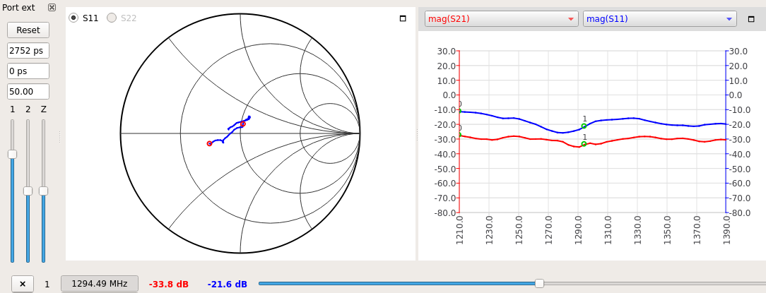
Slot sheet 300mm x 120mm with 10mm dip each side. Slot 228mm long, later tapered 6 to 16mm.
Bigger reflector and matching done
Broadband, not really.
==== Tapered slot ====
Broadband, better.
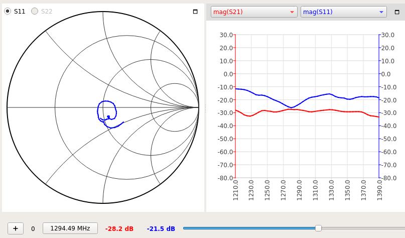
Reflector now 12.5mm 1mm wire mesh 270mm x 440mm.
Why the Slot? A reasonably wideband, easily matched small antenna for portable use. Sits close to a pole
and brings the vertical beamwidth (horizontal polarisation) down.
This may seem similar to the Long Alford Slot but these are very narrow bandwidth as determined by the pipe size.
Perhaps a waveguide slot antenna could be better at 2.4GHz but again the narrow bandwidth and thus construction accuracy
needs to be much better than what I can do.
Bending the edges of the rear shield up 23cm / 4, a bit more gain.
Build #3 so, easily tuned.
==== the Paper ====
https://www.academia.edu/718327/Radiation_Characteristics_of_Offset-fed_Slot_Antenna_of_Notebook_Computers_for_the_Reception_of_Digital_Terrestrial_TV_Broadcasting_including_the_Effects_of_Human_Hands_and_Liquid_Crystal_Display
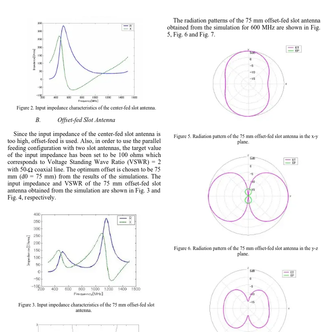
The structural parameters of the antenna are as follows: W= 300 mm, H = 210 mm, L = 250 mm, h0 = 10 mm, d1 = 25mm, d2 = 25 mm, d3 = 75 mm, d4 = 125 mm, and d0 = 0 mm (for the center-fed slot antenna,
.:. slot length 250mm, 10mm wide, designed for 600MHz, in Figure 2, we see at around 1200 MHz the impedance comes down nicely.